Transcription of Multifunctional time delay relay - Drivetek as
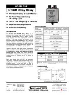
1 Multifunctional time delay relay MFT IQ13S. 4 functions Zoomvoltage: 24 .. 240 Vac/dc 1 output contact Function Q 4- functions E delay on A delay off I1 Pulse limitation timer voltage control B2 Cycling timer starting on a pause MFT IQ13S time ranges Adjustable 0,05 s .. 100 h Output relay 1 changer potential free 250 Vac / 8 A. Indicators Green LED ON: indication of supply voltage Green LED flashes: indication of time Yellow LED ON/OFF: indication of relay output Supply voltage 24 .. 240 Vac/dc -15% +10%. AC 48 .. 63 Hz, 100% duration of operation Reference data Selectron MFT Article no. MFT IQ13S 41130001. (Order data see chapter 1). ESG Multifunctional time delay relay MFT IQ13S. Technical data Input circuit MFT IQ13S. 24 .. 240 Vac/dc 4 VA / 1,5 W. Residual ripple for dc 10%. Drop-out voltage >30% of minimum rated supply voltage Control contact / Voltage controlled Parallel switching of loads possible Input not potential free terminals A1 - B1.
2 Trigger level (senitivity) automatic adapted to supply voltage Max. line length 10 m Min. control pulse lenght DC 50 ms / AC 100 ms Accuracy Base accuracy 1% of the scale limit Repeatability of the scale limit <0,5% or 5 ms Adjustment accuracy <5% of the scale limit Temperature influence 0,01% / C. Reaction times Recovery time 100 ms Type key I U 1 3 S. Construction Control I Mounting position S Voltage control functions Connecting voltage U Multifunction 3 24-240 Vac/dc Q 4 functions 4 12-240 Vac/dc T Cycling timer TU Cycling timer multifunction Output 1 1 changer 2 2 changers ESG Multifunctional time delay relay MFT IQ13S. Function descriptions E - delay on B2 - Cycling timer starting on a pause When the supply voltage U is applied, the set interval t begins When the supply voltage U is applied, the set interval t begins (green LED U/t flashes).
3 After the interval t has expired (green LED U/t flashes). After the interval t has expired, the U. U. LED U/t LED U/t R <t R t t t t (green LED U/t illuminated) the output relay switches into on- output relay R switches into on-position (yellow LED illumina- position (yellow LED illuminated). This status remains until the ted) and the set interval t begins again. After the interval t has supply voltage U is interrupted. If the supply voltage U is expired, the output relay switches into off-position (yellow interrupted before expiry of the interval t, the interval already LED not illuminated). The output relay is triggered in the ratio expired is erased and is restarted when the supply voltage U 1:1 until the supply voltage is interrupted. is next applied. A - delay off The supply voltage U must be constantly applied to the device (green LED U/t illuminated).
4 When the control contact U. LED U/t S t <t R t <t S is closed, the output relay R switches into on-position (yellow LED illuminated). If the control contact S is opened, the set interval t begins (green LED U/t flashes). After the interval t has expired (green LED U/t illuminated) the output relay switches into off-position (yellow LED not illuminated). If the control contact is closed again before the interval t (green LED U/t illuminated) has expired, the interval already expired is erased and is restarted with the next cycle. I1 - Pulse limitation timer voltage control When supply voltage U is applied, the output relay R switches into on-position (yellow LED illuminated) and the set interval t U. LED U/t R t <t begins (green LED U/t flashes). After the interval t has expired (green LED U/t illuminated) the output relay switches into off-position (yellow LED not illuminated).
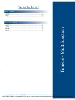
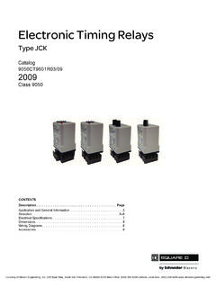
5 This status remains until the supply voltage is interrupted. If the supply voltage is interrupted before the interval t has expired, the output relay switches into off-position. The interval already expired is erased and is restarted when the supply voltage is next applied. ESG Multifunctional time delay relay MFT IQ13S. Connection MFT IQ13S. (+) (+). U ( ). U ( ). 15 S 15. A1 B1 A1 B1. A1 15 A1 15. R R. A2 16 18 A2 16 18. A2 A2. 16 18 16 18. Load limit curves MFT IQ13S. Switching voltage [Vdc]. 300. 200. 100. ohmic load 50. 40. 30. 20. 10. 0,1 0,2 0,5 1 2 5 10 20. Switching current [A]. Dimensions 87 mm 45 mm 87 mm 87 mm 45 mm 45 mm 5 mm 44 mm 17,5 mm 35 mm 60 mm ESG Multifunctional time delay relay MFT IU14S, IU24S. 7 functions Zoomvoltage: 12 .. 240 Vac/dc 2 output contacts Function U Multifunction E delay on A delay off I2 Pulse extension with control contact W2 Wiping on trailing edge E1 delay on with control contact I1 Pulse limitation timer voltage control MFT IU14S B2 Cycling timer starting on a pause time ranges Adjustable 0,05 s.
6 100 h Output relay 1 or 2 changers potential free 250 Vac / 8 A. Indicators Green LED ON: indication of supply voltage Green LED flashes: indication of time Yellow LED ON/OFF: indication of relay output Supply voltage MFT IU24S. 240 Vac/dc -10% +10%. AC 48 .. 63 Hz, 100% duration of operation Reference data Selectron MFT Article no. MFT IU14S 41130003. MFT UI24S 41130004. (Order data see chapter 1). ESG Multifunctional time delay relay MFT IU14S, IU24S. Technical data Input circuit MFT IU143S, IU24S. 12 .. 240 Vac/dc IU14S: 4 VA / 1,5 W IU24S: 6 VA / 2 W. Residual ripple for dc 10%. Drop-out voltage >30% of minimum rated supply voltage Control contact / Voltage controlled Parallel switching of loads possible Input not potential free terminals A1 - B1. Trigger level (senitivity) automatic adapted to supply voltage Max. line length 10 m Min.
7 Control pulse lenght DC 50 ms / AC 100 ms Accuracy Base accuracy 1% of the scale limit Repeatability of the scale limit <0,5% or 5 ms Adjustment accuracy <5% of the scale limit Temperature influence 0,01% / C. Reaction times Recovery time 100 ms Type key I U 1 3 S. Construction Control I Mounting position S Voltage control functions Connecting voltage U Multifunction 3 24-240 Vac/dc Q 4 functions 4 12-240 Vac/dc T Cycling timer TU Cycling timer multifunction Output 1 1 changer 2 2 changers ESG Multifunctional time delay relay MFT IU14S, IU24S. Function descriptions E - delay on contact S has no influence on the condition of the output relay When the supply voltage U is applied, the set interval t begins R. When the control contact is opened, the output relay (green LED U/t flashes). After the interval t has expired switches into on-position (yellow LED illuminated) and the set interval t begins (green LED U/t flashes).
8 After the interval t has expired (green LED U/t illuminated), the output relay U. swit-ches into off-position (yellow LED not illuminated). LED U/t During the interval, the control contact can be operated any R <t number of times. A further cycle can only be started when a cycle run has been completed. (green LED U/t illuminated) the output relay switches into on- position (yellow LED illuminated). This status remains until the E1 - delay on with control contact supply voltage U is interrupted. If the supply voltage U is interrupted before expiry of the interval t, the interval already The supply voltage U must be constantly applied to the expired is erased and is restarted when the supply voltage U device (green LED U/t illuminated).When the control contact is next applied. U. A - delay off LED U/t The supply voltage U must be constantly applied to the S.
9 Device (green LED U/t illuminated). When the control contact R t <t U. S is closed, the set interval t begins (green U/tLED flashes). LED U/t After the interval t has expired (green LED U/t illuminated). S t <t the output relay R switches into on-position (yellow LED. R t <t illuminated). This status remains until the control contact is opened. If the control contact is opened before the interval t S is closed, the output relay R switches into on-position has expired, the interval already expired is erased and is (yellow LED illuminated). If the control contact S is opened, restarted with the next cycle. the set interval t begins (green LED U/t flashes). After the interval t has expired (green LED U/t illuminated) the output I1 - Pulse limitation timer voltage control relay switches into off-position (yellow LED not illuminated). If When supply voltage U is applied, the output relay R switches the control contact is closed again before the interval t (green into on-position (yellow LED illuminated) and the set interval t LED U/t illuminated) has expired, the interval already expired is erased and is restarted with the next cycle.
10 U. LED U/t I2 - Pulse extension with control contact R t <t The supply voltage U must be constantly applied to the device (green LED U/t illuminated). When the control contact begins (green LED U/t flashes). After the interval t has expired (green LED U/t illuminated) the output relay switches into off-position (yellow LED not illuminated). This status U. remains until the supply voltage is interrupted. If the supply LED U/t voltage is interrupted before the interval t has expired, the S output relay switches into off-position. The interval t already R. expired is erased and is restarted when the supply voltage is t t next applied. S is closed, the output relay R switches into on-position (yellow LED illuminated) and the set interval t begins (green B2 - Cycling timer starting on a pause LED U/t flashes). After the interval t has expired (green LED When the supply voltage U is applied, the set interval t begins U/t illuminated) the output relay switches into off-position (green LED U/t flashes).