Transcription of NADCA Engineering and Design: Coordinate …
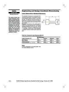
1 Engineering and design : Coordinate DimensioningNADCA Product Specification Standards for Die Castings / Section 4A / 20034A-6 The values shown repre-sent Standard Tolerances, or normal casting produc-tion practice at the most economical level. For greater casting accuracy see Precision Tolerances for this characteristic on the facing page. See Section 7, Quality Assurance for more toler-ance precision numbers indicate the degree of accuracy in calculating precision. The more significant numbers in a specified tolerance, the greater the accuracy. Signifi-cant number is the first non-zero number to the right of the decimal and all numbers to the right of that number. For example, The degree of accuracy is speci-fied by the three significant numbers 140. This is not to be confused with tolerance precision. A tolerance limit of has a higher degree of precision because it is closer to zero tolerance. Zero tolerance indicates that the part meets design specifications Standard and Linear Precision tolerances are expressed in thousandths of an inch (.)
2 001) or hundredths of a millimeter (.01).Notes: Casting configuration and shrink factor may limit some dimension control for achieving a specified Standard Tolerance on any of the features labeled in the adjacent drawing, dimension E1 will be the value shown in table S-4A-1 for dimensions between fea-tures formed in the same die part. Tolerance must be increased for dimensions of features formed by the parting line or by moving die parts to allow for movement such as parting line shift or the moving components in the die itself. See tables S-4A-2 and S-4A-3 for calculating precision of moving die compo-nents or parting line shift. Linear tolerance is only for fixed components to allow for growth, shrinkage or minor imperfections in the precision is the amount of varia-tion from the part s nominal or design feature. For example, a 5 inch design specifica-tion with tolerance does not require the amount of precision as the same part with a tolerance of The smaller the tolerance number, the more precise the part must be (the higher the precision).
3 Normally, the higher the precision the more it cost to manufacture the part because die wear will affect more precise parts sooner. Production runs will be shorter to allow for increased die maintenance. Therefore the objective is to have as low precision as possible without affecting form, fit and function of the AlloysZinc ( mm) ( mm)Aluminum ( mm) ( mm)Magnesium ( mm) ( mm)Copper ( mm) ( mm)Table S-4A-1 Tolerances for Linear Dimensions (Standard)In inches, two-place decimals (.xx); In millimeters, single-place decimals (.x)Length of Dimension "E1"Basic Toleranceup to 1" ( )Additional Tolerancefor each additional inch over 1" ( )NADCAS-4A-1-03 Standard TolerancesExample: An aluminum casting with a in. (127 mm) specification in any dimension shown on the drawing as E1 , can have a Standard Tolerance of inch ( mm) for the first inch ( mm) plus for each additional inch (plus mm for each additional mm). In this example that is for the first inch plus multiplied by the 4 additional inches to yield a total tolerance of In metric terms, for the first mm increments plus multiplied by the 4 additional mm to yield a total tolerance of mm for the 127 mm design feature specified as E1 on the drawing.
4 Linear dimension tolerance only applies to linear dimensions formed in the same die half with no moving Linear Dimensions: Standard TolerancesEngineering and design : Coordinate DimensioningNADCA Product Specification Standards for Die Castings / Section 4A / 20034A-8 Line Tolerance. Information from the Pro-jected Area Tolerance table S-4A-2 in com-bination with the formerly discussed Linear Tolerance table S-4A-1 give a true represen-tation of Parting Line Tolerance. Note that the tolerances in the table apply to a single casting regardless of the number of : An aluminum die casting has 75 in2 ( cm2) of Projected Area on the parting die plane. From table S-4A-2, Projected Area Tolerance is + This is combined with the total part thickness tolerance from table S-4A-1 to obtain the Parting Line Tolerance. The total part thickness including both die halves is in. (127 mm) which is measured perpendicular to the parting die plane (dimen-sion E2 E1 ). From table S-4A-1, the Linear Tolerance is for the first inch and for each of the four additional inches.
5 The Linear Tolerance of inches is combined with the Projected Area Tolerance of + to yield a Standard Parting Line Tol-erance of + in. or in metric terms mm from Linear Tolerance table S-4A-1 plus + mm from Projected Area Tolerance table S-4A-2 = + Line Tolerance is the maximum amount of die separation allowed for the end product to meet specified requirements of form, fit and function. This is not to be con-fused with Parting Line Shift Tolerance which is the maximum amount die halves shift from side to side in relation to one example of Parting Line Tolerance is the amount a door is allowed to be opened and still call it closed. An example of Parting Line Shift Tolerance is how well the door fits in the frame. Worn hinges may cause the door to drag on the floor so that it can not be closed and therefore not perform its intended function. Parting Line Shift Tolerance will be discussed later in this section. Parting Line Tolerance is a function of the surface area of the die from which material can flow from one die half to the other.
6 This is also known as Projected Area. Projected Area is always a plus tolerance since a completely closed die has 0 separa-tion. Excess material and pressure will force the die to open along the parting line plane creating an oversize condition. The excess material will cause the part to be thicker than the ideal specification and that is why Projected Area only has plus tolerance. It is important to understand that Table S-4A-2 (Projected Area Tolerance) does not provide Parting Line Tolerance by itself. Part thick-ness or depth must be factored in to give a true idea of Parting Line Tolerance. Parting Line Tolerance is a function of part thickness perpendicular to the Projected Area plus the Projected Area Tolerance. Part thickness includes both die halves to give a volumetric representation of Parting Casting Alloys (Tolerances shown are "plus" values only)Zinc+ (+ mm)+ (+ mm)+ (+ mm)+ (+ mm)+ (+ mm)+ (+ mm)Aluminum+ (+ mm)+ (+ mm)+ (+ mm)+ (+ mm)+ (+ mm)+ (+ mm)Magnesium+ (+ mm)+ (+ mm)+ (+ mm)+ (+ mm)+ (+ mm)+ (+ mm)Copper+ (+ mm)+ (+ mm)+ (+ mm)Table S-4A-2 Parting Line Tolerances (Standard) Added to Linear TolerancesFor projected area of die casting over 300 in2 ( cm2), consult with your die Area of Die Castinginches2 (cm2)up to 10 in2( cm2)11 in2 to 20 in2( cm2 to cm2)21 in2 to 50 in2( cm2 to cm2)51 in2 to 100 in2( cm2 to cm2)101 in2 to 200 in2( cm2 to cm2)201 in2 to 300 in2( cm2 to cm2)NADCAS-4A-2-03 Standard TolerancesThe values shown repre-sent Standard Tolerances, or normal die casting production practice at the most economical level.
7 For greater casting accuracy see Precision Tolerances for this characteristic on the facing page. See Section 7, Quality Assurance, for more stan-dard tolerance Shift:Parting line die shift, unlike parting line separation and moving die component tolerances, is a left/right relationship with possible consequences. It can shift in four directions, based on a combination of part features, die construction and opera-tion factors. It can occur at any time and its toler-ance consequences should be discussed with the die caster at the design stage to minimize any impact on the final die casting. Notes:All values for part dimen-sions which run across the die parting line are stated as a plus tolerance only. The die casting die at a die closed position creates the bottom of the tolerance range, , (zero). Due to the nature of the die casting process, dies can separate imperceptibly at the parting line and create only a larger, or plus side, Line: Standard TolerancesEngineering and design : Coordinate DimensioningNADCA Product Specification Standards for Die Castings / Section 4A / 20034A-10 Moving Die Components Tolerance can affect final part performance similar to Part-ing Line Tolerance.
8 When the core is fully inserted into the die, the minimum tolerance is zero. As excess material and pressure are exerted in the die, the core can slide out cre-ating an oversized condition. A MDC Toler-ance has been developed to ensure minimal impact on form, fit and function by specifying limits to the oversize to Parting Line Tolerance, MDC Standard Tolerance is a function of the Projected Area Tolerance plus Linear Toler-ance. Linear Tolerance is calculated based on the length of movement of the core slide along dimension E3 E1 . Table S-4A-1 is used to determine Linear Tolerance. The linear dimension is not the entire length of E3 E1 but the is only the length of the core slide from where the core slide first engages the die to its full insertion position. Linear dimension is normally perpendicular to the Projected Area. Projected Area is the area of the core head that faces the molten material. Projected Area Tolerance for moving die components is determined from table S-4A-3.
9 The open area (cavity) on the end view of the part in figure 4A-1B at the beginning of this section shows the projected area. Projected Area Tolerance plus Linear Tolerance provide MDC Standard Tolerance for the volume of the part. Note that the tolerances in the table apply to a single casting regardless of the number of TolerancesThe values shown repre-sent Standard Tolerances, or normal casting produc-tion practice at the most economical level. For greater casting accuracy see Precision Tolerances for this characteristic on the facing page. See Section 7, Quality Assurance, for more stan-dard tolerance :Moving die components, also called moving die parts , are most commonly core slides (or pulls) which are used to form inset holes or features in a casting. All values for Projected Area dimensions formed by moving die components are stated as a plus toler-ance only. The moving die component at the die closed position is the bottom of the tolerance range, (zero). Due to the nature of the die cast process (parting line separation, wear on moving die components, ), a moving die compo-nent can back out of a die creating only a larger or plus side : An aluminum casting has 75 in2 ( cm2) of Projected Area calculated from the core slide head facing the molten material.
10 From table S-4A-3, Projected Area Tolerance is + This is combined with the length of the core slide Linear Tolerance from table S-4A-1 to obtain the MDC Stan-dard Tolerance. The total core slide length of in. (127 mm) is measured from where the core engages the part to full insertion in the plane of dimension E3 E1 to determine Linear Tolerance length. From table S-4A-1, the Linear Tolerance is for the first inch and for each of the four addi-tional Linear Tolerance of inches is combined with the Projected Area Tolerance of + to yield a MDC Standard Tolerance of + in. MDC Metric Standard Tolerance is + mm = ( mm) + (+ mm). on dimensions formed by moving die Casting Alloys (Tolerances shown are "plus" values only)Zinc+ (+ mm)+ (+ mm)+ (+ mm)+ (+ mm)+ (+ mm)+ (+ mm)Aluminum+ (+ mm)+ (+ mm)+ (+ mm)+ (+ mm)+ (+ mm)+ (+ mm)Magnesium+ (+ mm)+ (+ mm)+ (+ mm)+ (+ mm)+ (+ mm)+ (+ mm)Copper+ (+ mm)Table S-4A-3 MDC Tolerances (Standard) Added to Linear TolerancesFor projected area of die casting over 300 in2 ( cm2), consult with your die Area of Die Castinginches2 (cm2)up to 10 in2( cm2)11 in2 to 20 in2( cm2 to cm2)21 in2 to 50 in2( cm2 to cm2)51 in2 to 100 in2( cm2 to cm2)101 in2 to 200 in2( cm2 to cm2)201 in2 to 300 in2( cm2 to cm2)Moving Die Components (MDC): Standard TolerancesEngineering and design .