Transcription of NanoSpray III Source - sciex.com
1 P 1 NanoSpray III Source Easy to Use, Robust, and Flexible Solution for Nanoflow Applications The combination of mass spectrometry (MS) and nanoflow liquid chromatography (nanoLC) techniques is a key element of proteomics research. The strength of nanoLC-MS is that it enables the analysis of limited amounts of biological sample with high sensitivity. The variety of chromatographic phases and column configurations now available has resulted in widespread use of nanoLC-MS to tackle a broad range of biological problems. However, the low solvent flow rates used in nanoLC make chromatographic optimization more challenging than higher flow-rate applications. It is therefore important that the nanoflow interface to the mass spectrometer be robust, easy to use, and flexible to provide optimum performance on a wide variety of applications.
2 There are many examples of established and emerging applications that place different requirements on the nanoLC Source and interface. The wide distribution of hydrophobic and hydrophilic peptides in protein digests usually requires the use of a broad LC solvent gradient to improve protein sequence coverage. Some applications require use of nanoLC tapered emitter tips with chromatographic material packed right in the tip. It is therefore essential to have a versatile and stable nanoflow ESI system that is robust to varied solvent composition, choice in chromatographic format and media and even polarity when analyzing proteomic samples in an automated mode. Key Features of NanoSpray III Source Simplified emitter tip and column replacement with low dead volume finger tight connections with quick release of spray assembly Rail-mounted sliding union allows flexibility to use any emitter tip lengths Nebulizer gas and HV connect directly to Source .
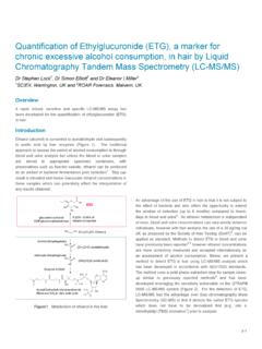
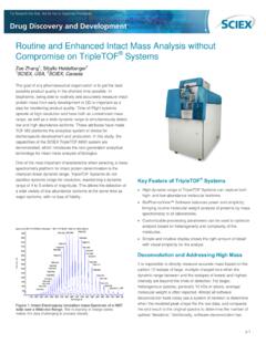
3 Sprayer assembly removes without the need to disconnect gas or HV Improved lighting and cameras for continuous spray visualization (new compact LCD monitors) Fixed angle spraying (~25 ) for easy spray tuning and limited interface contamination Source and nanoDCI heated interface compatible with SCIEX QTRAP and TripleTOF systems Optiflow Interface with nanoflow heater and curtain plate1 compatible with TripleTOF 6600 System Compatible with all nanoLC systems and column configurations, including sorbent-packed tapered emitter tips for high quality separations Figure 1. The NanoSpray III Source . The design provides an easy to use, robust and flexible solution for all nanoflow applications.
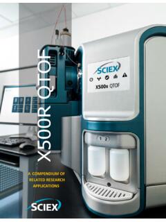
4 Cameras and illumination apparatus are not shown for clarity. p 2 New Camera and Light Source for Spray Visualization The spray from the emitter tip is now directly visualized on the monitors with high-gain cameras and laser light mounted on the NanoSpray III Source (Figure 2). The color camera employs digital signal processing for image control, and results in a clear, high contrast-ratio picture. The laser beam is positioned directly on the volume of the spray plume at the optimal spray tip position for easy visualization. This also provides a simple way of ensuring the correct spray tip position is used for every acquisition. This light diode has a built-in collimator lens in order to generate a beam that is more focused, in order to maximize the power density of the beam at the location of the spray tip.
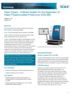
5 Fine adjustment of both camera and laser position is easily achieved through the addition of tool-free compression fittings that persist in place. Importance of Using the Heated Interface The heated interface of the NanoSpray Source is a particle discriminator interface (PDI), which provides maximum sensitivity for nanoLC applications2. As shown in Figure 3, the heated interface includes a heated laminar flow chamber located between the curtain plate and gas conductance-limiting orifice3. In addition to the drying effects of the Curtain Gas Interface, the laminar flow chamber may be heated from 80 to ~250 C to ensure sufficient desolvation across a wide liquid flow range. The flow of gas minimizes solvent introduction into the vacuum system.
6 Since the laminar flow chamber does not restrict the gas flow into the first vacuum stage of the mass spectrometer, its internal diameter is selected to consume a large portion of the ion plume. A gas-tight seal between the laminar flow chamber and the orifice is also critical, establishing laminar flow streamlines that converge upon the orifice to optimize ion transport into the vacuum system. The nanoDCI heater was the original design and is currently available on the QTRAP and TripleTOF Systems. Similar design concepts have gone into the OptiFlow Interface design, currently only available on the TripleTOF 6600 system. Flexible Configuration for Use with Any Column Type The flexible configuration of the NanoSpray III Source simplifies emitter tip and column replacement with advanced finger-tight fittings and conductive union connections.
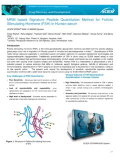
7 With the unique design of union mounting rail, the union can be fixed at any position along the rail to accommodate all types of emitter tips and column lengths. For applications where convenience, flexibility, and ease-of-use are top priorities, commercially packed columns are an excellent solution. These provide robust, reliable separation and are available with a selection of packing media for various sample types. The movable finger-tight union provides a consistent, low-dead-volume connection between the column and emitter tip to give optimum chromatographic performance and run-to-run reproducibility (Figure 4). Columns can be installed and disconnected easily without removing the spray assembly or the emitter tip.
8 Similarly, the finger-tight union enables tool-free replacement of emitter tips without disturbing the column connection. Figure 2. Continuous Visualization of Nanoflow LC Spray. The CCD camera and laser light Source enable the direct visualization of spray, to facilitate spray tuning and troubleshooting. Figure 3. Schematic of Heated Interface. Ions are generated within a few millimeters of the entrance to the heated laminar flow chamber. Two stages of desolvation are provided with the Curtain Gas interface and heated chamber. More favorable gas dynamics are provided by reduction of the curtain gas flow speed and establishment of laminar flow prior to the gas conductance limiting orifice. p 3 The flexibility of the Source also enables the use of tapered, fritted fused-silica tips packed with reverse-phase media.
9 The example shown in Figure 5 is an LC Multiple Reaction Monitoring (MRM) experiment using a tapered emitter tip packed with Zorbax C18 reverse-phase media. The observed peak widths are very good, with widths of ~10s at half height. The conductive assembly is compatible with the pre-column pressures generated by this configuration. Finally, the union mounting rail can be easily removed to allow installation of the OptiMS cartridge tip to interface the CESI 8000 plus system to the mass spectrometer (Figure 6). Used in conjunction with the heated interface, the extremely consistent sweet-spot of the interface allows for effortless and reproducible positioning of the sprayer for optimum sensitivity.
10 With the quick, tool-free column attachment and emitter tip replacement, the NanoSpray III Source offers unmatched ease-of-use and performance with no compromise. Polarity Switching and Spray Stability One common workflow in nanoLC applications involves rapid polarity switching during PTM Discovery experiments, where precursor ion scans are used to determine sites of phosphorylation. In order to assess the stability of the NanoSpray III Source during polarity switching, a 25 hour nano-flow injection acquisition (FIA) experiment was performed using Glu-Fibrinopeptide (GFP), where Q1 was continuously toggled between + and polarity every four seconds. As shown in Figure 7, the reproducibility of the signal across the 25 hour injection series was extremely high.