Transcription of NDT for Grinding Wheels - qnetworld.de
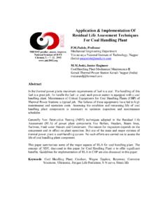
1 NDE2002 predict. assure. improve. National Seminar of ISNT Chennai, 5. 7. 12. 2002 NDT for G rinding Wheels , Dr. Annamalai M/s Carborundum Universal Ltd. and Introduction Grinding Wheels are a multipoint cutting tool composed of selectively sized abrasive grains held together by a bonding material. Abrasive materials are Aluminium oxide or Silicon Carbide in conventional range. Grinding is a process of material removal, which happens in the form of chips by the mechanical action of regularly shaped abrasive particles bonded together in a Grinding wheel . Grinding is done to get required Size, Form, and Finish. Grinding wheel is a multilayer consisting of minimum of 54% abrasive grain and 26% bond maximum with 15- 20% porosity that is shown in Fig 1. Our Objective was henceforth to identify a technique, which can locate cracks in the presence of pores by a NDT technique. Nomenclature of a Grinding wheel is as below is shown in Table 1.
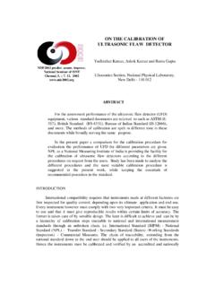
2 Table 1: Grinding wheel nomenclature (1) Type of abrasive Grain size Grade/ Hardness Structure Typ e of bond Manufacturer s reference A 36 L 5 V 23 23/80 Fig1. Grinding wheel A is the Aluminium oxide material. Grain size plays a part in Metal removal rate and also in the finish of the job for Grinding . Grit size representation is shown in Fig 2. Hardness represents the amount of grain to bond ratio in a Grinding wheel , which is tuned, based on application requirement. A represents soft wheel and Z represents a hard wheel . 5 represent the structure and the number varies from 2- 50. Number 2 represents dense structure and 50 represents open structure. Accordingly the porosit y vary from 15 % to as high as 40 %. V- represents Vitrified bond, B for resin bond Grinding wheel . /80 represent the speed at which the Grinding wheel can be operated. Process chart for making the Grinding wheel is shown below.
3 Usage pattern: Grinding Wheels are designed to run at speeds in the range of 33 mps to 80 mps Hence no small internal failure is accepted. Because if flaws are present they grow when the Wheels run and might lead to burst of the Wheels which will hit F ig 2: Grit S ize o f Ab ras ive Raw materials (Abrasive + BondMixing Moulding Dryin g Shaving Firing Finishing and QC Regular quality checks that are done on Wheels are visual inspection Geometry of the wheel Ring test Density of the wheel which relates to performance of the wheel Speed testing of the Wheels . Wheels are usually speeded to to 2 times depending on the application of speed before they are despatched. Hardness test Sometimes the Wheels do qualify critical test of the ring and speed test but still would break at customer end. Hence the need for introducing the NDT test for Wheels is felt. NDT methods for Grinding Wheels : Liquid penetrant method: This method identifies any pores or cracks of a material by application of kerosene or fluorescent dyes.)
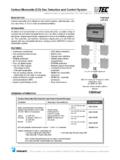
4 But for a Grinding wheel when applied, differentiation between inherent pores designed in a Grinding wheel would be mistaken for a defect. Hence this method was not useful. Magnetic and Eddy current testing methods warrant the material to be either electrically conducting or magnetically conducting which is ruled out for Grinding Wheels . Ultrasonic test methods: Pulse echo technique adopted and US waves are allowed to propagate in the material by means of a transducer. The US waves get reflected at interfaces, which are then received. Fig 4 shows the method of testing. the person operating and lead to severe injuries to fatal death. Hence the criticality of detecting internal failures are important. Fig 3 shows a Grinding wheel application for a tool and cutting application of a Grinding wheel Fig 3. Tool and cutter Grinding wheel application The elapsed time of sending and receiving the waves is measured.
5 Depending on the presence of the flaw the transit time will vary. Knowing the depth of the travel of the waves, velocity and thereafter the young modulus can be calculated. This method was attempted to check the Transit time of the wheel for interpretation. Values are stated below Table 2. Table 2. Transit time using Ultrasonic Instrument of a Grinding wheel Grad ing I5 K5 M5 Tim e( microseconds) Position 1st Posn 2nd posn 1st Posn 2nd posn 1st Posn 2nd posn C60 V1 7. 10 9. 00 6. 10 6. 00 3. 70 3. 90 C60 V1 5. 20 6. 30 7. 50 6. 70 4.
6 90 6. 30 C60 V2 6. 20 5. 70 7. 20 7. 10 6. 80 6. 10 C60 V2 4. 60 3. 90 6. 30 6. 10 7. 10 7. 00 The problem here as seen is there are a range of transit time seen within a same wheel when placed at different position. Also between one wheel to another the variation is so high even for a good product which had already passed all the qualifying test. If we were to assume the variation across hardness from I5 to K5 to M5, there also no trend analysis was possible. Such is the case, using Transit time values for interpreting a cracked wheel and a good wheel will be impossible. Acoustic methods: The process uses elastic waves to propagate in the material, which do not cause change in the materials being tested. WheelTransducers Wires to Ultrasonic instrument Fig 4.
7 Ultrasonic test m ethod u sin g V-meter This method is based on depending of natural oscillation frequencies (NOF) of article, being measured by the device, of physic and mechanical properties Of the material, including pores and flaws. Short pulse of ultrasonic energy is introduced in the test piece at regular interval of time and if the pulse encounters a reflecting surface, some or all energy is reflected. Based on the resonant frequency and the dimensions of the wheel , formula is used to find the young modulus of the wheel . As the whole article is taking part in the oscillation process in the natural frequency, measured value of NOF characterizes integral properties of the whole article. As for the control of pores that means, that measured value of NOF would depend not on the size of a single pore or micro flaw, but on their common quantity (percentage content). As for the macro flaws, this method can detect only quite big flaws, which change the specter of NOF.
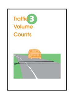
8 Hence we were not able to differentiate between a pore and a flaw. We are yet to explore this possibility. X-ray s: To identify the internal defects we went for X-rays radiography. X-ray imaging technique is an important tool for the real time radiographic inspection and it is commonly used in the medical and industrial application. These systems can be classified for the low and high X-ray energy applications. We applied an X-ray in the energy range of on the good wheel and also on the cracked wheel . The way on which they are exposed is shown in Fig 5. Results and discussion: X-ray sourceGood wheel Cracked wheel Energy of exposure: 45 kV Time of exposure: 1 second Fig 5. X-r ay exposur e of grind in g wh eel Below picture show the X-ray image photographed of the good and a defective wheel . Dotted marks in Fig 6 represents the Wheels being tested for hardness values at 6 places using an impact hardness testing machine.
9 While Fig 7shows a dark line running across the axis of the wheel which represents a crack in the wheel . Fig 6: X-ray i mage of a goo d wheel Fig 7: Xray image of a Cracked wheel Thus we were able to identify a crack in the presence of pore in a Grinding wheel . Our next process is to work out how to introduce the same for online testing. References: 1. Coes, Abrasives, Mcgraw Hill, 1967. 2. Non- destructive test methods - Symposium of NDT conference at IIT, Madras.