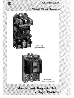
Transcription of NEMA Freedom Starters 1-77 Wiring Diagrams
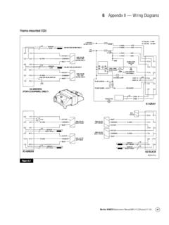
1 1999 NEMA Freedom StartersWiring DiagramsNon-reversing StarterNon-reversing Starter Single-Phase Non-combination260803 D1 Figure 1 Front View of PanelConnections for Non-reversing Starter3/142/13 Reset97969895T2T12/T14/T26/T3 OLL11L23MA1A21-Phase MotorT1T2124AC Lines3-Wire Control A StopStopStopStartStartStart2/1313/142/13 13/14 Remote Pilot Devices3/14 Not for Use with AutoReset OL Relays12-Wire ControlWhen More Than OnePushbutton Station IsUsed, Omit Connector A and Connect perSketch Below C Separate ControlRemove Wire C if Supplied andConnect Separate Control Lines tothe Number 1 Terminal on the RemotePilot Device and to the Number 96 Terminal on the Overload RelayNon-reversing Starter CombinationFigure 2 Fusible Control TransformerField Conversion to 1-PhaseFigure 1 Front View DiagramConnections for StartersConnections for Control StationsMMAdd DottedConnectionOLML3L2L1 OLMotor260878 D4A1A29695 OLReset2/133/14T124T26T36/T12/T2 T34/95 Reset9697981A1A2135T1T2T3 C T3T14/T2L11A1A2L23T26/L352/T1 MotorT1T2
2 Separate ControlRemove Wire C if Supplied andConnect Separate Control Lines tothe Number 1 Terminal on the RemotePilot Device and to the Number 96 Terminal on the Overload RelayOmit ConnectorStopStartRemote212/1343 Local13/14 Stop (OFF)Start (ON)Combined Remote and Local for Figures 1 and 2 Remote ControlLocal Control A When More Than OnePushbutton Station Is Used,Omit Connector A andConnect per Sketch BelowStopStartStartStopStart3/142/1312/1 313/142-WireControlNot forUse withAuto ResetOL / WhiteBlack / WhiteConnect to Coil Terminals A1 and A2 3443X1X212 Stop (OFF)43 Start (ON)3/142/131 BlackRedRed2431 HandAuto13/14 YellowYellowBlackRedFigure D2-Position Selector SwitchFigure ASTART/STOP PushbuttonsFigure BSTART/STOP Selector SwitchFigure C3-Position Selector SwitchHand3/14 YellowAuto1 BlackRemoteSwitchRed2143 Start (ON)3/141 BlackRedFigure EPilot Light (Motor RUN)Connect to A1 and A2 TerminalsTo CoilTerminal A1 Figure FSTART/STOP with Pilot Light3413/142/1321 Stop (OFF)Start (ON)Black / WhiteBlack / WhiteX1X2 LocalControl(Flange Mountingif Used)SeeFiguresA, B, C, D,E and FCPTF usible Control Transformer(If Used)
3 See Figure 2 Omit ThisConnectorif Figure 2Is or L2L3 FuseFuseFuse3 SecondaryConnectionsG1H31X2H24H4XF1H1X1 CPTP rimaryConnectionsConnections for DualVoltage Rated Transformer See Transformer NameplateRemove Wire C (Figure 1) if Usedand Connect as Shown Below.(All Other Starter Wires Remainas Shown in Figure 1) 1999 NEMA Freedom StartersWiring DiagramsReversing StarterReversing Starter Non-combinationReversing Starter CombinationFRFRFRA142(If Used)A1A25736A21 OLStarter Elementary DiagramRemote Control StationsL3L2L1 ACMotorT1T3T2 LinesContactors F and R areMechanically InterlockedOLOLRFFRFRLSRFLSF orwardReverseStop6357 FLSRLSWhen Limit Switches AreUsed.
4 Omit Connectors A and B and Connectper Dotted Lines657415531432F32 B A C T3T2AC MotorT1A2A1A2A1RT2T1T3OL96 Reset959798OL260844 D29596 C T3T2T12/4/6/Separate ControlRemove Wire C if Supplied and ConnectSeparate Control Lines to the Number 1 Terminal on the Remote Pilot Device and tothe Number 96 Terminal on the Overload DownPushbuttonPushbuttonForwardReverse31 Forward13426 Figure 1 Front View DiagramWire F Usedwith Local ControlPushbuttonsAC with FORWARDand REVERSE ButtonsElectrically D4A2 RLS752T14T2T12/T24/395 Reset6T3T36/5372123F1989796 OLRA1L241L13L35 FLS64563 Reverse4 Stop123443 ReverseForward153343 Forward251 Black/WhiteBlack/WhiteX2X1A195 Connect to A1 ofForward Coil and 95 of Overload RelayBlack/WhiteBlack/WhiteX2X1A1A2 Connect to ReverseCoil Terminals A1 and A2 Local ControlRemove Wire C (Figure 1) if Used andConnect as Shown Below (All Other StarterWires Remain as Shown in Figure 1)
5 H3 FuseFuseSecondaryConnectionsConnections for DualVoltage Rated Transformer See Transformer NameplateG1RA1A2L11X2L23L35X1H4H24 FuseH1XF1 CPT96 ResetOL95 PrimaryConnections1 ReverseForwardOFF53 BlackYellowBlueRedRedRedBlackBlueRedLoca lControl(Flange Mountingif Used)SeeFiguresA, B, Cand DFigure 1 Front View DiagramFigure 2 Fusible Control TransformerFigure APushbuttonsFigure B3-PositionSelector SwitchFigure CPilot Light(FORWARD)Figure DPilot Light(REVERSE)CPTF usible ControlTransformer(If Used)See Figure 2 Wire F Use withLocal Control Pushbuttons B A C or L2 L3A2A1 Remote Control withFORWARD andREVERSE (If Used)A1A25736A21 OLFigure 1 Elementary DiagramL3L2L1 ACMotorT1T3T2 LinesContactors F and R areMechanically MotorT1OL9596 C Separate ControlRemove Wire C When It Is Supplied.
6 ConnectSeparate Control Lines to the Number 1 Terminal on Remote Pilot Device, and to theNumber 95 Terminal on the Overload RelayWhen Limit Switches AreUsed, Omit Connectors A and B and Connectper Dotted 1999 NEMA Freedom StartersWiring DiagramsCover ControlNon-reversing Cover ControlNEMA 1 C400GK Control OptionsC400T Control OptionsReversing Cover ControlNEMA 1 C400GR Control OptionsC400T Control OptionsHandOFFAutoBlack 3/14 Red 1 HandAutoRed 1 Yellow - to CoilA1 Terminal Black 3/14 StartStopBlack 3/14 Red 1 Yellow 2/13 Local Control Options (If Used)Refer to Diagram Inside Enclosure for ConnectionsFigure ASTART/STOP Pushbutton B2-Position Selector C3-Position Selector Switch Lead fromCoil to Terminal Number 3260808 D1 Black A2 Black A1 Figure DPilot Light (Motor RUN)Black A1 Black A2 Figure FOverload TrippedWire C 1 OLConnect toOL TerminalNo.
7 96NC Interlock(If Used)orTestYellow - to CoilA1 TerminalReset95969798 BlackBlack1 RemoteSwitchStop1L1, X1 or 1 Figure ESTART/STOP with Pilot LightBlack 3/14 Yellow2/13 Red 1 StartStopFigure GPilot Light (Motor STOP)260810 D1 ForwardAdd Connector F Between Aux. ContactTerminals 2 and to Terminal A1 of theLeft Hand Coil and to TerminalNumber 95 of the Overload Relay Connect to Terminals A1 & A2of the Right Hand ContactorBlackBlackBlackBlackLocal Control Options (If Used)Refer to Diagram Inside Enclosure for ConnectionsFigure APushbuttonFORWARD/ STOP/ REVERSEF igure BPilot Light (FORWARD)Figure CPilot Light (REVERSE)3/1412/13 Local Control Options (If Used)Refer to Diagram Inside Enclosure for Connections260811 D1 Black/WhiteWire C 1 OLConnect to OLTerminal No.
8 96NC InterlockReset959697983 Start4 Stop12243143213443 Start31 AutoHand1 HandAuto1 Connect to CoilTerminals A1 & A2 Black/WhiteX1X2X1X2X2 Black /WhiteX1To CoilTo CoilSwitchRemoteYellowBlackRedRedYellowY ellowBlackBlackBlackRedRedRedStop1L1, X1 or 1 Black/WhiteBlack/WhiteBlack /WhiteFigure ASTART/STOPP ushbuttonsFigure BSTART/STOPS elector SwitchFigure C3-Position Selector Switch Figure D2-Position Selector Switch Figure FOverload TrippedFigure EPilot Light (Motor RUN)Figure GPilot Light (Motor STOP)260812 D1 to A1 ofForward Coil and 95 of Overload Relay34 Forward3251 Connect to ReverseCoil Terminals A1 & A2 53X1X2X1X2 Connect Wire F per DiagramBlueRedBlackBlueRedYellowRedRedBl ack/WhiteBlack/WhiteBlack/WhiteBlackLoca l Control Options (If Used)Refer to Diagram Inside Enclosure for ConnectionsFigure APushbuttonsFigure B3-Position Selector SwitchFigure CPilot Light (FORWARD)Figure DPilot Light (REVERSE)
9 1999 NEMA Freedom StartersWiring DiagramsMultispeedMultispeed 2-Speed 1-Winding Constant HorsepowerMultispeed 2-Speed 1-Winding Constant or Variable Torque260819 D3 Starter Elementary DiagramLinesSlowSlowSlowStopFigure CFigure BFastFastFastFigure 1 Motor ConnectionsConstant Horsepower MotorRemove Wire C if Suppliedand Connect as Shown Below.(All Other Wiring Remainsas Shown in Figure 1.)Control Circuit Transformer (If Used)A1A2L22 OLGX2X1XF1 FuseFuseFuseH1FL113H4 CPTR eset9596L35H31H24 Connections for Dual Voltage RatedTransformer See Transformer NameplatePrimaryConnectionsSecondaryConn ectionsFigure 2 Front View of PanelContactors F and 1S Are LinesWire F Used with LocalControl PushbuttonsOmit ThisConnection IfFigure 2 Is Used C SpeedSlowFastConnect LinesL1To Motor TerminalsL2L3 TogetherT6T1T4T2T5T3T4, T5.
10 T6 Remote Control StationsFigure B3 Slow4 Stop12346251 OFFX = Contact ClosedContactABPositionFastOFFXXSlowSlow ABFastFastFastSlow35613 Figure C52 Remove Wire C When It IsSupplied. Connect SeparateControl Lines to the Number 1 Terminal on the Remote ControlStation and the Number 96 Terminal on Overload Relay ControlCPTF usible ControlTransformer(If Used)See Figure 21OL 2OL124 FastOFFSlow52SF1SA1FA295 96 95 961S62F2S1L1354A1A2 Reset97969895T2T1T12/4/T2T3T36/1OL5L3L11 1L232SA1A2A2FA154322 OLT3T2T1956/2/4/Reset97969863F1SA2A12SF1 SA11SA2A11S2SA2695969596A1FA21OL 2 OLL21A1A245231S1OL2SF2OL2S1 OLF2OL2S1 OLF2 OLL1 L2 L3 ConstantHorsepowerMotorT4T4T1T3T5T3T5T2T 6T1T