Search results with tag "Wiring diagram"
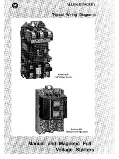
GI-2.0: Typical Wiring Diagrams
literature.rockwellautomation.comthe wiring diagrams (heavy lines). A wiring diagram gives the necessary information for actually wiring-up a group of control devices or for physically tracing wires when trouble-shooting is necessary. A line diagram gives the necessary informa- …

MCC Ratings - EandM
www.eandm.comunits with interwiring and interlocking between the starters to form a complete control system. Wiring diagrams, including the interwiring, is furnished. Class II is generally specified when a group of motors requires sequencing, interlocking, or interconnecting. Class II, Type B Class II, Type B wiring is similar to Class I, Type B wiring.

LT1 POWER MODULE WIRING DIAGRAM AND INSRUCTIONS
wiring-wizard.comWIRING DIAGRAM AND INSRUCTIONS Thank you for purchasing our product. We do everything we can to provide you with the most current and up to date diagrams. Please verify pin locations in these diagrams carefully and if they are incorrect email me at pmcmahon@nethere.net Ability to use a Digital meter is a must.
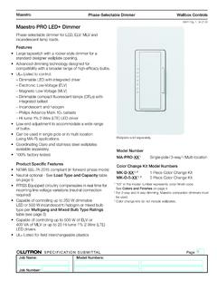
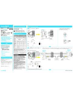
Maestro PRO LED+ Dimmer - Lutron Electronics Company Inc
www.lutron.comReverse MLV Transformer with Halogen4,5,6, 10 W 400 VA (300 W) ... Wiring Diagrams Single-Pole Wiring Line / Hot Neutral Black Brass Dimmer Blue Green Lighting Load 120 V~ ... Wiring Diagrams (continued) Dimmer Line Side Dimmer Load Side 4-Way Wiring (Using MA-R or MSC-AD Companion Dimmer)
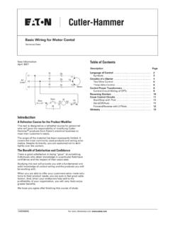
Basic Wiring for Motor Contol - Eaton
www.eaton.comBasic Wiring for Motor Contol Symbols Standardized symbols make diagrams easier to read. Both line and wiring diagrams are a language of pictures. It is not difficult to learn the basic symbols. Once you do, you are able to read diagrams quickly, and can often understand a circuit at a glance. The more you work with both line and

2080-UM004D-EN-E Micro800 Plug-in Modules User Manual
literature.rockwellautomation.comPlug-in Module Wiring Diagrams, publication 2080-WD002 Information on mounting and wiring the Micro800 RS232/485 isolated serial port plug-in module. Micro800 Non-isolated Unipolar Analog Input Plug-in Module Wiring Diagrams, publication 2080-WD003 Information on mounting and wiring the Micro800 non-isolated unipolar analog input plug-in module.

2004 COROLLA ELECTRICAL WIRING DIAGRAM
www.toyotadriver.ruWIRING DIAGRAM Provides circuit diagrams showing the circuit connections. 2004 COROLLA (EWD533U) 3 ... checking the system circuits which use a common ground may help you identify the problem ground quickly. The relationship between ground points ( EA, IB and IC shown below) can also be checked this way. 5 5 5 5 4 4 4 4 BA1 4 5 IB1 8 EA2 ID1 15 ...

472 WIRING DIAGRAMS - Discount Marine
www.discount-marine.comWIRING DIAGRAMS 477 13 Diagram Key Connectors Ground Frame ground No connection plugs Connection Starter relay unit Electric starter Term. blk batt. cables 3 6 5 2 Ignition coil Ignition coil Power relay Fuel injectors Fuel injectors Junction plug Battery charging coil/crankshaft position sensor Low press. Fuelpump driver High press. fuelpump relay

with Equipment Interface Module Installation Guide
customer.honeywell.com** See wiring diagrams on pages 4-5. *** See wiring diagram below for wiring Dry Contact Devices to display alerts. U1, U2, and U3 are normally ... Typical hookup of powered humidifier Typical hookup of non-powered humidifier ... 2.3b Push excess wire back into the wall opening. 2.4 Insert coin cell battery.

Steering Column Wiring Diagrams - Flaming River
www.flamingriver.comThis document will provide a wiring diagram and a brief overview on how the turn signal switch functions. Visit FlamingRiver.com for Tech Tips or call 1-800-648-8022 if additional assistance is required, we are happy to help! P/N: 102569, Rev A . 1 Turn Signal Switch, Male Connector

DOOR GARD FEATURES AND PROGRAMMING GUIDE …
amsasecurity.comSee the Wiring Diagram and Specifications for the relay electrical specifications. ... (or wire) marked WB (see wiring diagrams for location). 3. This feature does not work with the master code. 6050212 Rev. 1.1 4 www.ieib.com COMMAND AND CONTROL STYLES 212i INDOOR STYLE • Flushmount, indoor design 212w WEATHER RESISTANT STYLE • Flushmount ...

2080-UM001F-EN-E Micro810 Controllers User Manual
literature.rockwellautomation.comWiring Diagrams 2080-WD009 Information on mounting and wiring the Micro800 1.5" LCD Display and Keypad Module. Micro800 Programmable Controllers General Instructions 2080-RM001 Information on instruction sets for developing programs for use in Micro800 control systems. Industrial Automation Wiring and Grounding Guidelines, publication 1770-4.1
Bosch Type Relay Wiring Diagrams - Parts Express
www.parts-express.comBosch Type Relay Wiring Diagrams. 2. 3

York Retail System Specific Wiring Diagrams
www.virginiaair.com2 Stage HP 95% & 80%Single Stage X13 Gas Furnace HW VP 8000: WD19 2 Stage HP 1 Stage HP: 1 Stage HP WD7 ... Wiring Diagram WD 1. Optional. Optional. NOTES: If 10-wires between the Air Handler and the Heat Pump is not possible W1 and W2 can be combined at the AH.

DUAL BATTERY WIRING DIAGRAM
www.australiandirect.com.auWIRING KIT All of the wiring and gear you need to do the following. Install the KickAss Pack in a Caravan/Trailer Have the KickAss Pack in the back of the vehicle but also charge a battery in a Caravan/Trailer SKU : SDPTC12V12A7SL SKU : KAPW350 SKU : KACB-A2C SKU : BAVAN-EXT KickAss have a range of high quality Portable Solar Panels that
INSTALL RADIORA 2 RRD-PRO (044357a)
www.lutron.comLoad (light) will turn OFF and turn back ON to full intensity. This indicates a successful factory reset. ... Product may be permanently damaged. • Check wiring to be sure it matches installation instructions and wiring diagrams. All ILs are flashing. Over Current Protection Mode ... (9 m) of an RF signal repeater. For additional ...
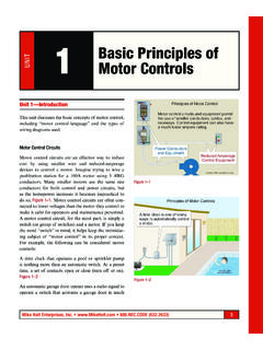
1 Basic Principles of - Mike Holt
www.mikeholt.comConnection diagrams, or wiring diagrams, show the components of the control circuit in a semblance of their actual physical locations. The start-stop push-button station is shown more as an actual device in the control circuit wired to a set of contacts marked 2 and 3. In Figure 1–4, the wires on each side of the M con-

Color Codes for RJ-45 Ethernet Plug - ZetaTalk
www.zetatalk15.comsequence because the wires may be crossed inside the jack. The jack should either come with a wiring diagram or at least designate pin numbers that you can match up to the color code below. There are two wiring standards for these cables, called T-568A and T-568B. They differ only in pin assignments, not in uses of the various colors.

Next Generation Guardmaster Safety Relay (GSR) Wiring …
literature.rockwellautomation.comWiring Diagram Next Generation Guardmaster Safety Relay (GSR) Bulletin 440R Quick Reference Page Safety Relay Modules Input Devices Output Devices SIL CL Category Number PL Stop Cat. 6 SI E-stop PowerFlex 525 2 3 d 0 8 SI Multifunctional Access Box (MAB) PowerFlex 525 2 3 d 0 10 SI Trojan T15 1794 FLEX I/O 2 3 d 0

Blue Easy Reader Thermostat - Emerson US
climate.emerson.comwiring schematic. 6. Push excess wire into wall and plug hole with a fire resistant material (such as fiberglass insulation) to prevent ... Wiring diagrams shown are for typical systems and describe the thermostat terminal functions.! WARNING ... 6 "Run" identifies button to begin normal operation.
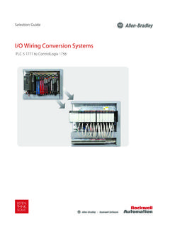
I/O Wiring Conversion Systems, PLC-5 1771 to ControlLogix …
literature.rockwellautomation.comWiring Diagram Cat. No. Qty. Cat. No. Qty.(2) (2) Where two is indicated, these modules need to be located directly next to each other in the 1756 chassis. Cat. No. (3) (3) An “F” at the end of the 1756 catalog number indicates that it is fused to match the …
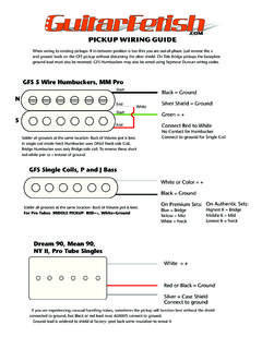
Pickup Wiring Guide - Guitarfetish
www.guitarfetish.comStrat® Wiring Diagram Wire Highest Ohm (K) To Bridge, Lowest to Neck. 5-Way Switch Vol 250K Tone 2 250K Tone 1 250K GND GND Connect to Bridge Ground To Ouput Jack + Black to Ground Black to Ground Black to Ground BRIDGE MIDDLE NECK.047uf Pro Tubes-Red= + White= Ground Suggested Pot and Cap Values Pots

Maintenance Manual MM-0888 RSSplus™ Trailer ABS with …
sealcocvp.comABS Indicator Lamp (on Trailer) 8 Types of Faults 9 Section 4: System Configurations RSSplus™ Installation Diagrams 17 Multiple Trailer Applications P5E 18 P5 19 Wiring Diagrams Power Cable Lift Axle 20 Section 5: Diagnostics Diagnostics Important PLC Information for Blink Code Diagnostics TOOLBOX™ Software 21 Vista™/Windows 7 Installations

Analog input module AI 4xRTD/TC 2-/3-/4-wire HF (6ES7134 ...
cache.industry.siemens.comwiring and commissioning of the SIMATIC ET 200SP distributed I/O system. The STEP 7 online help supports you in the configuration and programming. Device information Product manuals contain a compact description of the module-specific information, such as properties, wiring diagrams, characteristics and technical specifications. General information
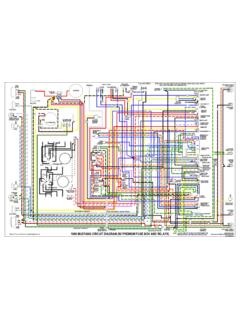
66 Mustang Wiring Diagrams (Colorized)1 - Clan Mcmuffin
www.clanmcmuffin.comTurn signal flasher Headlight harness Main Disconnect Turn signal connector Glove compartment light Heater Hazard flasher Hazard flasher switch Gauge Feed Wiring Main Disconnect Ignition switch Stop Light switch Tail light harness, Blk to tail light, Blk/Red to backup lights, Yel/Wht to fuel sending unit. Connect Red/Blu wire to neutral switch ...

RightSight Photoelectric Sensors - Rockwell Automation
literature.rockwellautomation.com• Fixed focus diffuse • Transmitted beam • Small aperture fiber optic The following laser models are available: • Polarized retroreflective ... Wiring Diagrams 6 Approximate Dimensions [mm (in.)] 6 Typical Response Curves 7 Cordsets and Accessories 8. 2 Rockwell Automation Publication 42EF-TD001B-EN-P - January 2019 RightSight ...
HS26-060-1P GCS16-090-350-2Y - Lennox
www.lennox.comto Lennox in regard to repair parts, literature, wiring diagrams, etc. Use of proper unit identification numbers and serial numbers will greatly help in expediting any material required for these products. Model Numbers Each unit manufactured is a …
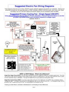
Suggested Electric Fan Wiring Diagrams - DaveBarton.com
www.davebarton.comAug 28, 2016 · turn on fans when temp sensor is activated 12v switched wire. may be green wire at a/c clutch. note: or in an ’84 to ‘89 240 you may use the a/c power ‘on’ wire: red/white wire at ac switch microswitch in dash.optional diodes signal 12v switched (fuse panel) power “on” when key is in the “run” position power source should be
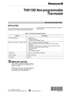
TH5110D Non-programmable Thermostat
customer.honeywell.comWIRING DIAGRAMS Fig. 6. Typical hookup of conventional 1H/1C system with one transformer. Fig. 7. Typical hookup of conventional 1H/1C system with two transformers. Fig. 8. Typical hookup of 1H/1C heat pump. Fig. 9. Typical hookup of heat only system. M22068 G O/B W Y C R Rc L1 (HOT) FAN RELAY COMPRESSOR CONTACTOR L2 R C 1 2 3 POWER SUPPLY.

Thermostat E Installation Guide - Google Nest
nest.comUse the wiring diagram you got from the compatibility checker in step 4 to connect your system wires to the Nest Thermostat. Note: If you have an R, Rc or Rh wire, you can put it into the R connector on the Nest Thermostat. If you have a W2, Y2 or O/B wire, you can put it into the * O/B connector, if needed. The exposed wire should be straight ...

Service Manual for InSinkErator Commercial Disposers
insinkerator.emerson.comConnection Wiring Diagram attached to the inside of the disposer terminal box cover for the correct voltage connections. Standard disposer voltages are: • 115/208/230 volts for single phase electrical power • 208/230/460 volts for three phase electrical power NOTE: All amp ratings denote amp draw during a grind load.
PEL
hubbellcdn.comSee page 9 for wiring diagram 10 Only available with 0-10V drivers. Universal voltage only. Not available with HM or HH lumen outputs 11 GTD and ATSD available for 120-277V and EU, fixed output, driver options only NX In-Fixture Control Options: 12 NX only available with 0–10V dimming drivers. Contact factory for NX compatibility with 480V

Manual-ON Occupancy Sensor - Leviton
www.leviton.commanually pressing the push-button. The lights will remain ON as long as the unit detects activity in the ... TYPICAL SPECIFICATIONS n Operating Temperature Range: 0°C to 50°C n Storage Temperature Range: -10°C to 85°C ... WIRING DIAGRAMS

ES-FA-9AA and ES-FA-11AA E-Stop Safety Module
info.bannerengineering.comAn Emergency Stop Safety Module is used to increase the control reliability of an emergency stop circuit. As shown in the wiring diagrams, the models ES-FA-9AA and ES-FA-11AA E-Stop Safety Modules are designed to monitor a 1-channel or 2-channel E-stop switch. A 2-channel E-stop switch has two electrically isolated contacts. WARNING :

standards & regulations - Legrand
www.legrandgroup.com2 way switch Compact fluorescent lamp Fluorescent lamp Lamp Lamp Socket outlets Socket outlets ... American standard 48 Residential wiring diagram 50 Overview of the installation and related ... 3 European plug 4 Israeli 5 Italian 6 Euro-US 7 Chinese 8 Indian 04. F Fiji Finland France French Overseas Territories G Gabon

VisionPRO™ 8000 Touchscreen Programmable Thermostat
customer.honeywell.comSCREWS (2) WALL ANCHORS (2) WIRES THROUGH WALL AND WIRE SLOT CONVENTIONAL SCREW TERMINALS HEAT PUMP M19951 Y2 L E AUX S1 S2 Y2 W2 S1 S2 RC R O/B Y G C RC R W Y G C Table 1. Selecting Terminal Identifications for System Type. System Type Wallplate Terminal Identifications Wiring Diagram Reference Standard …
NEW VINTAGE INSTRUMENT AND GAUGE KIT INSTALLATION ...
newvintageusa.comUse the included wiring diagrams to help guide your wire routing Use 14 ga. wire on all connections to ... Fuel level: 240-33 w/ sender, 0-90, 73-10, 0-30 The fuel gauge range (ohms) must match sender 1. Locate suitable positions foryour gauges. ... Push the button, drive a measured mile, do not turn off ignition, stopping and starting movement ...

Elite Series CBA27UHE Units
tech.lennoxintl.comVII Wiring Diagrams and Sequence of Operations Page 32..... The Elite CBA27UHE units are high efficiency blower coils featuring an all-aluminum coil. Several models are avail able in sizes ranging from 1‐1/2 through 5 tons (5.3 through 17.6 kW). The CBA27UHE is an upflow horizontal unit de signed for HCFC-410A refrigerant.
WIRING INFORMATION FOR HUMBUCKER PICKUPS
www.sixstringzone.comPARALLEL WIRING Parallel wiring connects the coils of a humbucker like two independently functioning single coils. The result is a brighter, more single-coil like tone but without losing hum-canceling. A humbucker wired in parallel has about 30% less output of the same pickup wired in series. More wiring diagrams for
Wiring Diagram Book - Daltco
www.daltco.comPUSH BUTTON, SELECTOR SWITCH, LIMIT SWITCH, ETC. FIBER OPTIC CABLE ELECTRICAL CONNECTIONS ... Wiring Diagrams 55-57 Type S AC Combination Magnetic Starters.....58-59 Class 8538 and 8539 58-59 3-Phase, Size 0-5 58 ... Typical Controller Markings Typical Elementary Diagram IEC
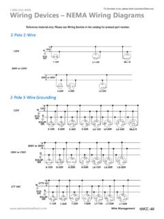
Wiring Device NEMA Wiring - AutomationDirect
cdn.automationdirect.comWiring Devices – NEMA Wiring Diagrams 600V AC 600V AC 600V AC G EQUIP. GR. L17-30R 3-Pole 4-Wire Grounding Continued 3ø 600VAC 18-15R 18-20R 18-30R1 8-50R 18-60R

WIRING DIAGRAMS - Vintagesnow.com
www.vintagesnow.comMODEL DIAGRAM OUTPUT PAGE (watt) (watt) (watt) Elan 04-01-3 60!60 5/21 75/23 Safari Citation 04-01 -4 60/60 5/21 160 Tundra, Tundra L T 04-01-4 60/60 5/21 160 ... Wiring color code The first color of a wire is the main color, second color is the stripe. Example: YL/ BK is a yellow wire with a black stripe.

WIRING DIAGRAMS - 73-87ChevyTrucks.com
www.73-87chevytrucks.commore practical to use a single wire protected by a braided tubing called a loom. Wiring harnesses are joined by using a multiple plug and receptacle connector block, or a terminal post chassis junction block. In the instrument panel area plastic insulated blade-type connectors and screw-type terminals are used.
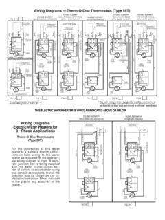
Wiring Diagrams — Therm-O-Disc Thermostats (Type 59T)
users.snowcrest.netGrounding conductor may be required. Refer to Wiring Section of Manual * This water heater is factory equipped for two (2) wire connection to electrical power.

WIRING DIAGRAM INDEX - Volvo Trucks
www.volvotrucks.usrly20 ign+ 86 85 30 87 f60 30a hvac fan a b f84 15a power door locks b f79 25a lcm4 a b f61 5a lvd sens/ vendor ttu a b x41 b+, ejb a e c f b d f76 30a ds open seat suspension b f41 30a

WIRING DIAGRAMS - 73-87ChevyTrucks.com. Classic Chevy ...
www.73-87chevytrucks.comright is the engine, instrument panel, cab and taillight Circuits can also be traced by following the circuit ... Then a small current flows through the heating wire, keeping the strip hot and the contacts open. This ... sis junction block. In the instrument panel area plastiC insulated blade-type connectors and screw-type termi ...
WIRING DIAGRAMS - uCoz
gershon.ucoz.comtransmission should be in park. a manual transmission should be in neutral. warning: operate the engine only in a well-ventilated area. warning: keep away from moving parts when the engine is running, especially the fan and belts. warning: to prevent serious burns, avoid contact with hot parts such as the radia-tor, exhaust manifold(s), tail ...
Similar queries
WIRING DIAGRAMS, The wiring diagrams, WIRING DIAGRAM, Wiring, Diagram, Starters, MODULE WIRING DIAGRAM AND INSRUCTIONS, Lutron Electronics Company Inc, Reverse, Side, Basic Wiring for Motor Contol, Eaton, Diagrams, Read, Read diagrams, 2080, Help, 472 WIRING DIAGRAMS, Typical, Push, And Specifications, Specifications, 212i, Micro810, Parts Express, 2 Stage, Stage, Turn, Signal, 1 Basic Principles of, Mike Holt, Control, Button, Plug, Safety Relay, Emerson, Wiring Conversion, Trailer, Turn signal, Rockwell Automation, Focus, 42EF, HS26-060-1P GCS16-090-350-2Y, Lennox, Thermostat, Google Nest, Nest Thermostat, InSinkErator, Electrical, 10V dimming, Leviton, Standards, Standard, Series CBA27UHE Units, PUSH BUTTON, MODEL DIAGRAM, Single, Terminal, Junction, Chevy, Engine, Small, Block, Transmission