Transcription of WIRING INFORMATION FOR HUMBUCKER PICKUPS
1 WIRING INFORMATIONFOR HUMBUCKER PICKUPST hank you for purchasing a Seymour Duncan pickup. With proper installation, this pickup will provide you with excellent tone. If you have no experience with soldering we recommend you find an experienced tech to install your new pickup. 5427 Hollister Barbara, CA 93111-2345(805) 964-9610, Fax (805) 964-9749 WHAT IS A HUMBUCKER ? A HUMBUCKER is a pickup design consisting of two coils, which are connected electronically out of phase and with opposite magnetic polarities. The effect of this design is to cancel hum and other extraneous noise. PICKUP POSITIONS:The main difference between bridge and neck/mid-dle PICKUPS is output. There is naturally less string vibration closer to the bridge, so bridge PICKUPS are generally wound hotter than neck/middle PICKUPS to compensate for this.
2 Calibrating the PICKUPS this way allows for a more even output balance between the neck and bridge positions. FOUR-CONDUCTOR WIRING :A HUMBUCKER with a four-conductor lead wire gives you direct access to each of the coils, which gives you access to a variety of WIRING options. In addi-tion to series WIRING (which is standard humbucking operation), a four-conductor lead wire allows coil-splitting, parallel WIRING , phase switching, and more. For more info regarding WIRING options visit the FAQ, Tech Tips, Schematics, and Forum sections of our website: HUMBUCKER WIRING COLOR CODES:Most Seymour Duncan humbuckers with four- conductor wires use the following color code: Green = beginning of adjustable coil (South)Red = finish of adjustable coilBlack = beginning of stud coil (North)White = finish of stud coilAdjustable coil = south magnetic polarityStud coil = north magnetic polarity STANDARD HUMBUCKING OPERATION (series WIRING )With a 4-Conductor HUMBUCKER : the RED & WHITE wires are soldered together and taped, the GREEN & BARE wires are connected to ground, and BLACK wire is the hot a single-conductor HUMBUCKER .
3 The inner, black wire is the hot output, and the outer braided shield gets connected to ground. COIL SPLITTING Sometimes incorrectly referred to as coil-tapping, coil-splitting is a WIRING option that shuts off one coil, resulting in a single-coil Strat-like tone. To switch from series to split, use the diagram below (hum-canceling will be lost when you switch to split mode). For more coil-splitting diagrams visit our schematics section at: WIRINGP arallel WIRING connects the coils of a HUMBUCKER like two independently functioning single coils. The result is a brighter, more single-coil like tone but without losing hum-canceling. A HUMBUCKER wired in parallel has about 30% less output of the same pickup wired in series. More WIRING diagrams for switching between series and parallel are available in our schematics section at: OF PHASE WIRINGOut of Phase WIRING is the electrical linking of two PICKUPS (or coils) in either series or parallel but with the signal polarities combined in a way that audibly cancels out part of the signal.
4 Usually the low frequencies are canceled and the result is a thin, and nasal sounding tone. For more phase-switching diagrams visit our schematics section at: HOW TO INSTALL A PICKUPTo install a pickup in your instrument, you need screwdrivers, wire cutters, wire strippers, electrical tape, rosin core solder, solder wick and a soldering iron. Don t use a soldering gun: it can demagnetize the PICKUPS . If you are not confident in your solder-ing abilities, take your guitar to a qualified tech. A few dollars spent wisely at this juncture can save many dollars later, and maybe your instrument. Follow these general steps and you should be on your ) Remove the strings from the guitar. This will make it easier to remove PICKUPS , mounting rings, and/or pickguards without scratching the ) Remove pickguard or control cavity covers.
5 If you have to lay the pickguard on the top of the guitar, place a soft cloth over the guitar s body to protect it from ) Draw a diagram of the guitar s current WIRING . Pay attention to the wires from the existing PICKUPS , make note of their color and where they are con-nected. That way, you will always have a reference to the original ) De-solder the PICKUPS from where they are currently connected and clean any excess solder from the parts with solder wick. It will be easier to solder the wires from your new PICKUPS onto a clean surface than one with solder splattered all over it. 5) Remove (unscrew) the old PICKUPS from the mounting rings (or pickguard) that were holding them in place. Once removed, store the original PICKUPS in a safe, dry place away from magnetic interference.
6 This will keep them safe and functional for future use (especially important if it is a vintage instrument). 6) Install the new PICKUPS into the mounting rings or pickguard where the old PICKUPS were, making sure that you retain the proper orientation. 7) Run the new wires back to the controls to which the old PICKUPS were attached to (either a volume pot or a selector switch). Measure the wires to the proper length (long enough to make it to the con-nections with about an inch or so extra for slack), cut and strip the wires, and carefully solder them into place. Use our diagrams to help you if our wire color-code is different from the PICKUPS in your ) Reattach the pickguard and/or control cavity covers, string up the guitar, adjust the pickup height (see below), and test your new PICKUPS out.
7 PICKUP HEIGHT ADJUSTMENTThe closer you put a pickup to the strings, the more output you will get from that pickup. In the neck position, the string vibrates much wider (louder) than in the bridge position, so the neck pickup does not usually need to be set quite as close to the strings as a bridge recommends that when the strings are pressed down at the highest fret:A neck HUMBUCKER be set 1/8 from the bridge HUMBUCKER be set 1/16 at the high E-string, and 3/32 at the low , you need to let your ears be the judge, but these guidelines should point you in the right SUPPLIERSFor a comprehensive list of guitar parts suppliers, visit the following link: #parts ADDITIONAL WIRING DIAGRAMSFor access to a large number of WIRING diagrams visit the schematics section of our website at.
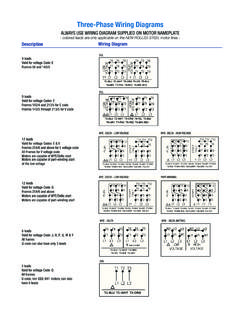
8 "White""Red""Black" Hot Output"Green" GroundedShield GroundedGroundSPDTon/none/on mini-toggle"White""Red"Shield GroundedOutput to controlsyou getseries/parallel series/split/parallel"Green""Black"using DPDT on/none/on DPDT on/on/on Chassis groundedParallelSplitSeries"White" and "Red"Soldered togetherand tapedShield GroundedHot OutputDPDTon/none/on mini-toggle"Green""Black"Pickup Hook-up DetailSeymour Detail for 4 Conductor Pickup CA- Pickup SelectorB- Solder the braided shield to the back of volume for bridge pickup C- Solder Hot output hereD- Volume for Neck pickupE- Tone for bridge pickupF- Tone for Neck pickup G- Output JackH- Ground/SleeveI- Hot/Tip J- Green & Bare solder to back of potK- Red and White solder together and insulated L- Black wireGHDEFS tandard HUMBUCKER Wiringneck pickupbridge pickupPart No.
9 501005-110 Rev B