Transcription of NEW VINTAGE INSTRUMENT AND GAUGE KIT INSTALLATION ...
1 NEW VINTAGE INSTRUMENT AND GAUGE KIT INSTALLATION INSTRUCTIONSAIR CORE GAUGES WOODWARD, 1967, 1940, PERFORMANCEREV120414 INDEXTHE BASICS, TOOLS AND SENDERSSPEEDOMETER QUICK SET-UPINSTALLATION DIAGRAMSPROGRAMMABLE SPEEDOMETER SUPPLEMENTALTROUBLESHOOTING page 2page 3page 4-7page 8-13page 14 Thank you for choosing New VINTAGE USA products. We strive to provide the finest quality and design components available on the market. If you need technical assistance, please call or email VINTAGE USA 5-Year WarrantyNew VINTAGE USA warrants all merchandise against defects in workmanship and materials for 60 months.
2 After the 60 month period, a pro-rated service fee of no more than 50% production costs may be applied. This warranty applies to all instrumentation products, excluding senders. The warranty does not apply toa product used in a manner for which it was not designed, of if it has been altered in any way.; New VINTAGE USA LLC is not responsible for any damage or costs associated with any product that has been purchased. This is a limited warranty as identified in the Magnunson-Moss Warranty Act of ServiceService can be obtained during the normal warranty period by contacting New VINTAGE and obtaining a Return Authorization Number (RZA#).
3 New VINTAGE will repair or replace any item found to be defective and return ship to no cost via ground or post office services. Other shipping/international services will be applied at additional cost. Buyer is responsible for shipping to New VINTAGE for warranty repair. Return shipping will be the responsibility of the customer if the product is found to be damaged or out of warranty. An RZA number must be obtained and proper return/warranty form accompanied with the product. Missing items/ReturnsMissing items/returns must be processed within 15 days of end user receiving the product.
4 All returned must be shipped back to the place of purchase. Any return shipping costs to New VINTAGE are the responsibility of the purchaser. An RZA number must be obtained and proper return/warranty form accompanied with the product. A restocking fee not to exceed 10% may be applied to items that must be repackaged. Any item returned in a non-usable condition will be returned or charged to the items must be reported within 15 days of receiving the product. Items found to be missing will be shipped via ground or postal service at no charge. Expedited/international shipping options are available at an additional charge.
5 It is the policy of New VINTAGE to quickly replace any items that may be missing in a timely manner but not to overnight or expedite shipping in any way at no YOU BEGIN:Read these instructions out your wiring scheme ahead of time. Use the included wiring diagrams to help guide your wire routingUse 14 ga. wire on all connections to sending units. Use electrical solder and heat shrink tubing or appropriate solder less connectors to make all wiring connectionsDisconnect the vehicle's batteryDo not use thread sealer on the sending units, they have a tapered threadHave a plan. Mock up parts or layout as needed.
6 It takes a little more time, but will save time and money in the Tools and Materials Needed for Installation14 and 16 ga. stranded wireSpade or Bullet connectorsMomentary push -buttonPressure sender for hour meterElectrical solder (optional)Heat shrink tubing (optional)Soldering iron (optional)Measuring tape or rulerEngine adaptors for senders4 3/8 hole sawWire cuttersWire stripper/crimperFilesVarious hand tools:wrenches, screwdriver, etcInstallation of gauges:2. Slide GAUGE through hole and add backing clamp over the retaining studs. Using the included washers and nuts, tighten to a snug fitWiring the gauges:Run the power wiring from the gauges to an appropriate positive (+) on the fuse block after the battery.
7 This applies to the switched 12V+ and GAUGE lightingConnect the ground to a good dedicated ground on the chassisRun each wire to the appropriate sender and use the proper connector for each item (eyelet, spade, etc.) from the sender to the dash. Leave some extra slack in the wire and label that wires will not chafe on holes by using grommets and that they will clear any moving wires are run from the appropriate sender location to the gauges location, connect to the corresponding wire on the Packard connector with solder and heat shrink tubing or a solder less : The 4-3/8" speedometer lighting is wired via tabs on the back.
8 The bulb is a GE 194 The 3-3/8" speedometer lighting is LED lighting which is internal, no replacement is installationYou must use senders with the proper ohm match for your GAUGE , using mis-matched senders will result in improper readings on your temperature ohmThe water temperature sender has a 1/8 NPT end. It should be installed close to the thermostat on the intake manifold. There are usually ports for temperature on the block in the water jackets, which can be used as pressure. 240-33ohm The sender has a 1/8 NPT end on it. Check for your factory location for a pressure port and level: 240-33 w/ sender, 0-90, 73-10, 0-30 The fuel GAUGE range (ohms) must match sender1.
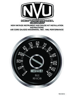
9 Locate suitable positions foryour gauges. The gauges fit in a 4-3/8" and/or 3-3/8" holes. Take note of the anti-rotation notches and add this feature where THE ELECTRONIC SPEEDOMETERWith the key on, in normal operating position, press the remote pushbutton for approximately 2 seconds. The word HELLO will appear in the odometer windowPUSH 2 the button is released, it will read "CLR ODO" scroll through the menu by briefly pressing the button and the 3rd item will be "self HI" push BRIEFLY2 TIMESWait 4 seconds and "PENDING will appear. The speedometer is now waiting for input to start counting pulses per mile.
10 push the button , drive a measured mile, do not turn off ignition, stopping and starting movement is OK. "SELF HI" will appear while 4 secAt the end of the mile, push the button again, "CALCING" will appear briefly. push the button 2 more times to "DONE" your speedometer is now calibrated, enjoy. You may repeat the process as many times as needed. The setting will be stored in the CALIBRATING THE MECHANICAL SPEEDOMETERYour mechanical speedometer has a universal 1:1 drive ratio. If your stock speedometer was accurate before, this one has tyhe sdame drive is achieved by changing the vqaroius drive grars in your transmission.