Transcription of Ladder Diagram Example - SIU
1 1 2 3 4 5 6 7 8 9 10 11 12 13 14 15 16 17 18 19 20 21 22 23 24 25 26 27 28 29 30 31 32 33 34 35 36 37 38 39 40 41
1 2 3 4 5 6 7 8 9 10 11 12 13 14 15 16 17 18 19 20 21 22 23 24 25 26 27 28 29 30 31 32 33 34 35 36 37 38 39 40 41
Typical wiring MECH. pera ese LOAD LOAD Typical Applications Reversing Motor starters. Reclose Relay Cut-out ... 0 o 0 o 0 o 0 0 o o o o . ... push button switches. Develop a ladder logic diagram to implement this control. et438b-7.pptx . Design Example: Reciprocating Motion
Domain:
Source:
Link to this page:
1 1 2 3 4 5 6 7 8 9 10 11 12 13 14 15 16 17 18 19 20 21 22 23 24 25 26 27 28 29 30 31 32 33 34 35 36 37 38 39 40 41
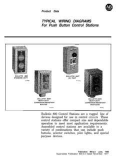
Typical Wiring Diagrams For Push Button Control Stations 3 Genera/ Information @ Each circuit is illustrated with a control circuit (continued) schematic or line diagram and a control station wiring diagram. l The schematic or line diagram includes all the components of the control circuit and indicates their
WIRING DIAGRAMS m c w Syfnbol Devise Symbol Plugging Relays H-q+- (P4Of.t Shown) Closing On Opening On Rising Press. Press. T T T T Closing On Opening On Rising Temp. Rising Temp. Pressure and Temperature Thermal Overload Push Button Standard L LLLQ 0 NC NO rLl3 IiL 0 0 Mushroom Head Push Button Heavy Duty, Oiltight Switches
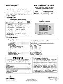
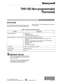
wiring schematic. 6. Push excess wire into wall and plug hole with a fire ... Wiring diagrams shown are for typical systems and describe the thermostat terminal functions.! WARNING ... 1 “Heat" “A/C” “Off” identifies button. When filled indi-cates system mode selected.
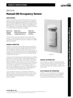
manually pressing the push-button. The lights will remain ON as long as the unit detects activity in the ... TYPICAL SPECIFICATIONS n Operating Temperature Range: 0°C to 50°C n Storage Temperature Range: -10°C to 85°C ... WIRING DIAGRAMS
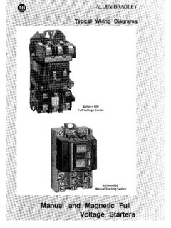
PUSH BUTTON, SELECTOR SWITCH, LIMIT SWITCH, ETC. FIBER OPTIC CABLE ELECTRICAL CONNECTIONS ... Wiring Diagrams 55-57 Type S AC Combination Magnetic Starters.....58-59 Class 8538 and 8539 58-59 3-Phase, Size 0-5 58 ... Typical Controller Markings Typical Elementary Diagram IEC
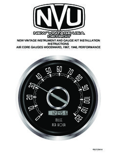
Use the included wiring diagrams to help guide your wire routing Use 14 ga. wire on all connections to ... Fuel level: 240-33 w/ sender, 0-90, 73-10, 0-30 The fuel gauge range (ohms) must match sender 1. Locate suitable positions foryour gauges. ... Push the button, drive a measured mile, do not turn off ignition, stopping and starting movement ...
WIRING DIAGRAMS Fig. 6. Typical hookup of conventional 1H/1C system with one transformer. Fig. 7. Typical hookup of conventional 1H/1C system with two transformers. Fig. 8. Typical hookup of 1H/1C heat pump. Fig. 9. Typical hookup of heat only system. M22068 G O/B W Y C R Rc L1 (HOT) FAN RELAY COMPRESSOR CONTACTOR L2 R C 1 2 3 POWER SUPPLY.
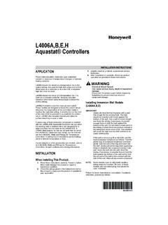
Disconnect power supply before connecting wiring to avoid electrical shock or equipment damage. All wiring must comply with local codes and ordinances regarding wire size, insulation, enclosure, etc. See Fig. 4 and 5 for typical diagrams of Aquastat® Controllers used in heating systems. Use these Aquastat Controllers with copper wire only. Fig. 4.

Wiring LED’s in line is usually simpler. This can also be used for a route if you wish to show the position of every turnout. To show the route selected with a single LED, the LED is powered at the panel and grounded through contacts on the Tortoise machines. This gives a CTC “feel” to the panel. Push the button, hear the