Transcription of VisionPRO™ 8000 Touchscreen Programmable Thermostat
1 PRODUCT DATA68-0280-01 Registered Trademark 2011 Honeywell International Inc. All Rights Reserved VisionPRO 8000 TouchscreenProgrammable ThermostatAPPLICATIONThe VisionPRO 8000 Touchscreen Programmable Thermostat is an effortless, 7-Day Programmable Thermostat that provides universal system compatibility, precise comfort control and is TH8110 Thermostats provide temperature control for gas, oil, electric and heat pumps for 1 heat, 1 cool systems. The TH8320 Thermostats provide temperature control for gas, oil, electric and heat pumps for up to 3 heat, 2 cool systems including dual fuel TH8321 Thermostats provide temperature control for gas, oil, electric and heat pumps for up to 3 heat, 2 cool systems including dual fuel operation plus dehumidification Large, clear display with backlight shows the current and set temperature and time even in the dark.
2 Menu-driven programming make setup effortless. Beautiful ergonomic design is smart and sophisticated to match your customers lifestyle. Touchscreen interaction Real-time clock keeps time during power failures and automatically updates to daylight savings. "Saving Changes" notification lets you know when the schedule changes have been saved. Change/check reminders let you know when to service or replace filters or batteries. Various Hold options allow you to override the program schedule, as desired. Speedy same-schedule programming no need to copy multiple days. Armchair programming allows you to remove the Thermostat from the wall for programming. Programmable fan offers increased air quality when combined with a Honeywell whole-house air 1 Specifications/Ordering Information.
3 2 Installation .. 4 wiring .. 5 Power the Thermostat .. 11 Installer Setup .. 15 Installer System Test .. 21 Programming .. 38 VisionPROTM 8000 Touchscreen Programmable Thermostat68-0280 012 ORDERING INFORMATIONWhen purchasing replacement and modernization products from your TRADELINE wholesaler or distributor, refer to the TRADELINE Catalog or price sheets for complete ordering you have additional questions, need further information, or would like to comment on our products or services, please write or local Honeywell Automation and Control Products Sales Office (check white pages of your phone directory). Customer Care1985 Douglas Drive NorthMinneapolis, Minnesota 55422-4386In Canada Honeywell Limited/Honeywell Limit e, 35 Dynamic Drive, Toronto, Ontario M1V Sales and Service Offices in all principal cities of the world.
4 Manufacturing in Australia, Canada, Finland, France, Germany, Japan, Mexico, Netherlands, Spain, Taiwan, United Kingdom, Description:Electrical Ratings:Temperature Setting Range:Heating: 40 F to 90 F( C to 32 C).Cooling: 50 F to 99 F (10 C to 37 C).Operating Ambient Temperature:TH8000 VisionPRO Thermostats: 0 F to 120 F (-18 C to 49 C).C7089U: -40 F to 120 F (-40 C to 49 C).C7189U: 45 F to 88 F ( C to 32 C).Shipping Temperature:TH8000 VisionPRO Thermostats: -30 F to 150 F ( C to C).Operating Relative Humidity (Non-condensing):TH8000 VisionPRO Thermostats: 5% to 90%.C7089U: 5% to 95%.C7189U: 5% to 95%.Humidity Setting Range (TH8321 models only):Cooling: 40% to 80% Display Range (TH8321 models only):0% to 99%.Cycle Rates (at 50% Load):Heating: Selectable 1 - 12 cycles per : Selectable 1 - 6 cycles per :TH8000 VisionPRO Thermostats: Premier White Wall Mount Remote Indoor Sensor: Premier White Accuracy: +/- 1 minute per : Three replaceable AAA alkaline batteries: Power thermostats when 24 Vac common is not used.
5 Non-replaceable lithium battery with ten-year life under normal use to hold calendar and time settings. Alkaline batteries keep calen-dar and time after lithium battery is no longer Characteristics of Remote Sensors:C7089U Outdoor Sensor: Negative temperature coefficient (NTC) means that resistance decreases as the temperature increases. See Table 13 in the Operationsection for sensor resistance Remote Indoor Sensor: Negative temperature coefficient (NTC), means that resistance decreases as the temperature increases. See Table 14 in the Operation section for sensor resistance Indication: TH8000 VisionPRO Touchscreen Thermostats show "Cool On" on the screen when Cool is Indication: TH8000 VisionPRO Touchscreen Thermostats show Heat On on the screen when Heat is methods Battery only Common wire only Common wire with battery backupSystem types (up to 3 heat/2 cool or up to 1heat/1cool, depending on model) Gas, oil or electric heat with air conditioning Warm air, hot water, high-efficiency furnaces, heat pumps, steam and gravity Heat only includes power to open and power to close zone valves (series 20) and normally-open zone valves Heat only with fan Cool only 750 mV heating systemsChangeoverManual or Auto changeover selectableSystem settingHeat-Off-Cool-Auto (Em.)
6 Heat for heat pumps)Fan settingAuto-On-CircTerminalVoltage (50/60 Hz)Running CurrentW Heating20 - 30 - Heating (Powerpile) 750 mV dc100 mA dcY Cooling20 - 30 - Fan20 - 30 - .60 AVisionPROTM 8000 Touchscreen Programmable Thermostat368-0280 01 Auxiliary Heat Indication: TH8000 VisionPRO Touchscreen Thermostats show Aux. Heat On on the screen when Auxiliary Heat is Heat Indication: TH8000 VisionPRO Touchscreen Thermostats show Heat On on the screen when Emergency Heat is activated and the System mode is in the Em. Heat position. Calibration: C7089U, C7189U and TH8000 VisionPRO Touchscreen Thermostats are factory-calibrated and require no field Differential: TH8000 VisionPRO Touchscreen Thermostats operate with droopless control. Once the Thermostat senses that 1st stage is running at 90% capacity, the Thermostat energizes 2nd :Mounting Means:TH8000 VisionPRO Touchscreen Thermostat : Mounts directly on the wall in the living space using mounting screws and anchors provided.
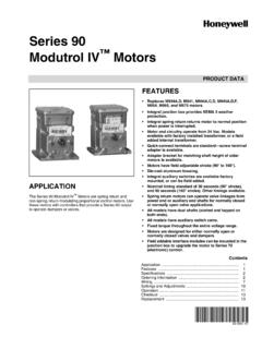
7 Fits a vertical or horizontal 2 x 4 in. junction Outdoor Sensor: Mounts outside of living space with mounting clip and screws Remote Indoor Sensor: Mounts directly on the wall using mounting screws and anchors provided. Fits a vertical 2 x 4 in. junction Plate:32003796-001 Cover Plate is used to cover marks left on the wall by the old :TH8000 Touchscreen Thermostat : see Fig. Outdoor Sensor Mounting Clip: see Fig. Cover Plate: see Fig. Remote Indoor Sensor: see Fig. 1. TH8000 Touchscreen Thermostat dimensions in in. (mm).Fig. 2. C7089U Outdoor Sensor Mounting Clip dimensions in in. (mm).Fig. 3. 32003796-001 Cover Plate dimensions in in. (mm).SeriesSystem StagesApplicationPower and System ChangeoverVisionPRO 8000 Touchscreen11 - 1H/1C32 - 3H/2C0 - Standard1 - Humidity SensorU - Universal (Auto changeover and/or manual change-over) dual powered, system flexibility, schedule (152)THERMOSTAT4-9/16(116) 3-3/8 (86)WALLPLATE 3-3/8 (86) THERMOSTATAND WALLPLATE1-3/8 (35)M44881-1/2 (38)7-7/8 (200)3-5/16 (84)3-5/16 (84)M221395-1/2 (140)VisionPROTM 8000 Touchscreen Programmable Thermostat68-0280 014 Fig.
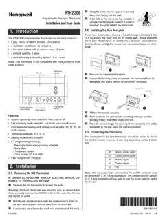
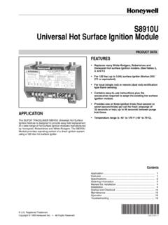
8 4. C7189U Remote Indoor Sensor dimensions in in. (mm).INSTALLATIONWhen Installing this these instructions carefully. Failure to follow the instructions can damage the product or cause a hazard-ous the ratings given in the instructions to make sure the product is suitable for your must be a trained, experienced service completing installation, use these instructions to check out the product LocationInstall the Thermostat about 5 ft. ( ) above the floor in an area with good air circulation at average temperature. See Fig. 5. Fig. 5. Selecting Thermostat not install the Thermostat where it can be affected by: Drafts or dead spots behind doors and in corners. Hot or cold air from ducts. Radiant heat from sun or appliances. Concealed pipes and chimneys.
9 Unheated (uncooled) areas such as an outside wall behind the WallplateCAUTIONE lectrical cause electrical shock or equipment power before Thermostat can be mounted horizontally on the wall or on a 4 in. x 2 in. ( mm x mm) wiring and level the wallplate (for appearance only). a pencil to mark the mounting the wallplate from the wall and, if drywall, drill two 3/16-in. holes in the wall, as marked. For firmer material such as plaster, drill two 7/32-in. holes. Gently tap anchors (provided) into the drilled holes until flush with the (117)4-5/8(117)2-3/4 (70)2-3/4 (70)1-1/8 (29)FRONT VIEWSIDE VIEWFRONT VIEW (COVER OFF)3-1/4(83)5 FEET[ METERS]YESNONONOM19925 VisionPROTM 8000 Touchscreen Programmable Thermostat568-0280 the wallplate over the holes, pulling wires through the wiring opening.
10 See Fig. the mounting screws into the holes and 6. Mounting (FIG. 9 - 21)All wiring must comply with local electrical codes and ordinances. set of terminal identifications (Table 1) that corresponds with system type (conventional or heat pump in Fig. 7). the screws for the appropriate system type selected; see Table 1. See Table 2 for terminal designation descriptions. Insert wires in the terminal block under the loosened screw. See Fig. tighten each excess wire back into the the hole with nonflammable insulation to prevent drafts from affecting the Fig. 9 through 21 for typical wiring 7. Selecting terminal identifications for system 8. Inserting wires in terminal Use 18 gauge Thermostat HOLESM19916 MOUNTING SCREWS (2)WALL ANCHORS (2)WIRES THROUGH WALLAND WIRE SLOTCONVENTIONALSCREW TERMINALSHEAT PUMPM19951Y2 LEAUXS1S2Y2W2S1S2 RCRO/BYGCRCRWYGCT able 1.