Transcription of PP901A & B Pressure Reducing Valves - Honeywell
1 PP901A & B Pressure Reducing Valves DESCRIPTION The PP901A & B Pressure Reducing Valves regulate the Pressure of air delivered to pneumatic control system devices. The PP901A operates in a single Pressure system and delivers a regulated air Pressure . The PP901B operates in a two- Pressure system and delivers two independent regulated air pressures. The PP901A & B include a safety relief valve that protects the downstream line from excessive main line Pressure surges. A gage connection accommodates a 305915 0-30 psi Gage ( Gage ) for measurement of the regulated Pressure . BEFORE INSTALLING NOTE A coalescing filter is required upstream of the PP901A & B. Also, if no Gage is used, PP901 installation requires a CCT1705T 1/8-inch Pipe Plug.
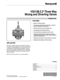
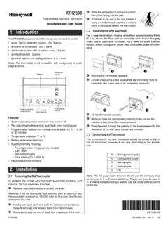
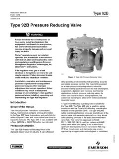
2 INSTALLATION INSTRUCTIONS INSTALLATION Mounting Refer to job drawings and Fig. 1. Mount PP901A or B in one of the following ways: Wall- or panel-mounted using provided Bracket. Bracket includes mounting slots for two 1/4-20x5/ 8 inch screws (provided). Directly supported on system piping Piping Connect PP901A & B INLET and OUTLET piping (Fig. 1). Mount Gage or CCT1705T Pipe Plug in 1/8-inch NPT gage connection on PP901A & B. Registered Trademark Copyright 1996 Honeywell Inc. All Rights Reserved 95-2558 PP901A & B Pressure Reducing Valves 3-1/4 (83) TOP VIEW 1-3/8 (35) 2-5/16 (59) 1-7/8 (48) POSITION BRACKET UPWARD OR DOWNWARD 1/4-IN NPT INLET AND OUTLET 1/8-IN NPT GAUGE CONNECTION 1/8-IN NPT REMOTE PILOT CONNECTION (PP901B) 5/8 (16) 1-1/2 (38) 3-1/4 (83) 3-1/64 (77) 3-31/32 (101) 7/8 (23) FRONT VIEW SIDE VIEW OUT EXHAUST PORTS IN M12004 Fig.
3 1. PP901A & B Dimensions in Inches (Millimeters). Calibration Primary Reduced Pressure Setting The PP901A & B is factory set for a regulated outlet Use the following procedure to change the regulated Pressure of 18 psi (124 kPa). The safety relief valve is (primary) outlet Pressure to the desired system Pressure . factory set between 22 and 25 psi (152 and 172 kPa). PP901A (Fig. 2) NOTE: The following procedures require that a Gage is Loosen locknut and turn Pressure Reducing adjust mounted in the 1/8-inch NPT gage connection on ment screw clockwise to increase regulated outlet the PP901A & B. Pressure . Tighten locknut to maintain position of Pressure Reducing adjustment screw.
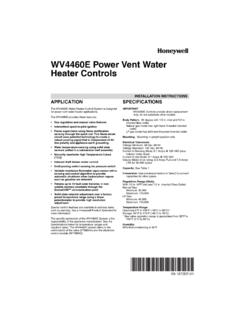
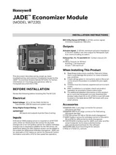
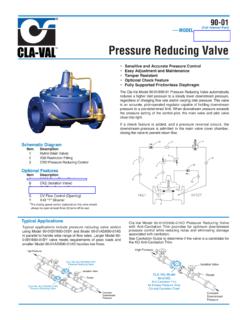
4 95-2558 2 PP901A & B Pressure Reducing Valves PP901B (Fig. 4) Turn Pressure Reducing adjustment screw clockwise to increase primary (lower) Pressure . (For primary Pressure , the Pressure Reducing adjustment screw on the PP901B does not have a locknut.) M12017 Pressure Reducing ADJUSTMENT SCREW VENTLOCKNUT Pressure Reducing ADJUSTMENT SPRING PILOT DIAPHRAGM PILOT VALVE SPRING PILOT VALVE DIAPHRAGM Pressure LINE RESTRICTION ASPIRATOR TUBE INLET OUTLET DIAPHRAGM CHAMBER DIAPHRAGM WEIR INTERNAL RELIEF VALVE INTERNAL RELIEF VALVE SPRING Fig. 2. PP901A Schematic. Safety Relief Pressure Setting Use the following procedure and refer to Fig. 3 and 4 to change the safety relief valve Pressure : Using a spanner wrench or similar tool, turn safety relief Pressure adjustment screw inward as far as it turns.
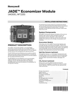
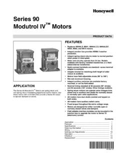
5 Adjust primary reduced Pressure setting (per Primary Reduced Pressure Setting procedure) until it exceeds the desired safety relief Pressure setting. Slowly back off safety relief Pressure adjustment screw until Gage reads the desired safety relief Pressure setting. Reset the Pressure Reducing adjustment screw for the desired reduced Pressure (per Primary Reduced Pressure section). RELIEF Pressure SPRING CUP AND Fig. 3. PP901A & B Safety Relief Valve. ADJUSTMENT SCREW GUIDE ASSEMBLY RELIEF VALVE SPRING SAFETY RELIEF VALVE M12005 Secondary Reduced Pressure Setting (PP901B Only) Use the following procedure and Fig. 4 to change the secondary (higher) Pressure to the desired system Pressure .
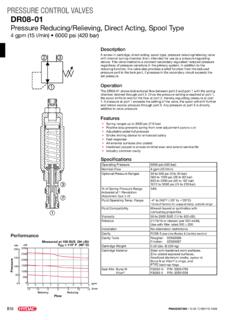
6 NOTE: Perform the Primary Reduced Pressure Setting procedure before this procedure. Position switching mechanism to allow air passage into switchover chamber. Loosen locknut on Pressure Reducing adjustment screw. Rotate secondary Pressure adjustment nut a few turns in either direction until Gage reads desired secondary Pressure . Tighten locknut to maintain position of Pressure Reducing adjustment screw. M12012 Pressure Reducing ADJUSTMENT SCREW SWITCHOVER Pressure INLET VENT LOCKNUT POINT "A" Pressure Reducing ADJUSTMENT SPRING DIAPHRAGM CUP SWITCHOVER CHAMBER SWITCHOVER DIAPHRAGM PILOT DIAPHRAGM DIAPHRAGM Pressure LINE ASPIRATOR TUBE SECONDARY Pressure ADJUSTMENT NUT INLET OUTLET Fig.
7 4. PP901B Schematic with Switchover Chamber. ENGINEERING DATA SpecificationsModels: PP901A : For single Pressure systems PP901B: For two- Pressure systems Pressure Range: Inlet: 45 to 150 psi (310 to 1034 kPa) Outlet: 0 to 25 psi (0 to 172 kPa); factory set at 18 psi (124 kPa) Maximum Airflow: 10 scfm ( m/s) at 18 psi (124 kPa) Safety Pressure Relief: Adjustment Range: 12 to 25 psi (83 to 172 kPa) Factory Setting: 22 to 25 psi (152 to 172 kPa) Capacity at 20 psi (138 kPa) outlet: 5 scfm ( m/s) Switchover (PP901B): Two-position pilot switch actuated electrically or pneumatically. Pressure relief feature exhausts Pressure difference. Adjustment Range: 0 to 5 psi (0 to 35 kPa) Factory Setting: psi (31 kPa).
8 5 psi ( kPa) over low setting 3 95-2558 PP901A & B Pressure Reducing Valves Connections: Inlet and outlet: 1/4 in. NPT (female) Gage: 1/8 in. NPT (female). Remote Pilot (PP901B): 1/8 in. NPT (female) Accessories: 14004205-002 Coalescing Filter For PP901B switchover: RP418A/B Electric-Pneumatic Relay or SP470A/B Two-Position Pneumatic Switch 14003638-001 Mounting Kit Operation PP901A & B (Fig. 2) A given Pressure Reducing adjustment screw setting creates a force on the pilot diaphragm by tension on Pressure Reducing adjustment spring. This force moves the internal relief valve against the pilot valve and causes the pilot valve to move downward and off its seat.
9 As high Pressure air enters the valve through the INLET, it passes between the weir and the diaphragm and onward to the valve OUTLET. At the same time, air travels through the open pilot valve, diaphragm Pressure line, and diaphragm chamber until its Pressure equals that of the inlet Pressure . As downstream Pressure increases, air Pressure builds beneath the pilot diaphragm through the aspirator tube connection with the downstream line. Downstream Pressure and air Pressure beneath the pilot diaphragm continue to rise. The force acting on the pilot diaphragm overcomes the force of the Pressure Reducing adjustment spring. This action forces the pilot diaphragm and internal relief valve upwards and allows the pilot valve to return to its seat.
10 With the pilot valve on its seat, air in the diaphragm Pressure line cannot escape and is trapped in the line. Air continues to enter the diaphragm chamber through the small restriction in the diaphragm and Pressure builds up in the diaphragm chamber. This Pressure forces the diaphragm against the weir and cuts off air flow through the valve. A small reduction in the downstream Pressure now causes the pilot diaphragm to force the pilot valve off its seat. This allows main line Pressure to leak from the diaphragm chamber through the diaphragm Pressure line and pilot valve to the downstream side of the system. When this side of the system reaches its preset Pressure , the pilot diaphragm moves upwards and closes the pilot valve.