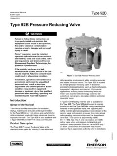
Transcription of Pressure Reducing Valve - Flow and Control
1 Pressure Reducing ValveTypical ApplicationsTypical applications include Pressure Reducing Valve stationusing Model 90-01BY/690-01BY and Model 90-01AS/690-01 ASin parallel to handle wide range of flow rates. Larger Model 90-01BY/690-01BY Valve meets requirements of peak loads andsmaller Model 90-01AS/690-01AS handles low DiagramItem Description1 Hytrol (Main Valve )2X58 Restriction Fitting3 CRD Pressure Reducing ControlOptional FeaturesItem DescriptionAX46A Flow Clean StrainerBCK2 (Isolation Valve )CCV Flow Control (Closing)*DCheck valves with Isolation ValveSCV Flow Control (Opening)Y X43 "Y" Strainer*The closing speed Control (optional) on this Valve shouldalways be open at least three (3) turns off its PressureIsolation ValveGaugeConstantDownstreamPressureCLA- VAL 90-01BY/690-01 BYPressure Reducing ValveCLA-VAL 90-01AS/690-01 ASPressure Reducing Valve Sensitive and Accurate Pressure Control Easy Adjustment and Maintenance Tamper Resistant Optional Check Feature Fully Supported Frictionless DiaphragmThe Cla-Val Model 90-01/690-01 Pressure Reducing Valve automaticallyreduces a higher inlet Pressure to a steady lower downstream Pressure ,regardless of changing flow rate and/or varying inlet Pressure .
2 This valveis an accurate, pilot-operated regulator capable of holding downstreampressure to a pre-determined limit. When downstream Pressure exceedsthe Pressure setting of the Control pilot, the main Valve and pilot valveclose a check feature is added, and a Pressure reversal occurs, thedownstream Pressure is admitted in the main Valve cover chamber,closing the Valve to prevent return Model90-01 KOAnti-Cavitation Trimfor Excess Pressure DropConsult Cavitation ChartIsolation Valve Gauge Constant Downstream Pressure High Pressure Cla-Val Model 90-01KO/690-01 KOPressure Reducing Valvewith Anti-Cavitation Trim provides for optimum downstreampressure Control while Reducing noise and eliminating damageassociated with Cavitation Guide to determine if the Valve is a candidate forthe KO Anti-Cavitation (Full Internal Port)690-01(Reduced Internal Port)Note.
3 The top two flange holes on Valve size 36 are threaded to 1 1/2"-6 90-01(Uses Basic Valve Model 100-01)Dimensions(In inches)Model 90-01 Dimensions(In Inches)ComponentStandard Material CombinationsBody & CoverDuctile IronCast SteelBronzeAvailable Sizes11 4" - 36"11 4" - 16"11 4" - 16"Disc Retainer &Diaphragm WasherCast IronCast SteelBronzeTrim: Disc Guide, Seat & Cover BearingBronze is StandardStainless Steel is OptionalDiscBuna-N RubberDiaphragmNylon Reinforced Buna-N RubberStem, Nut & SpringStainless SteelFor material options not listed, consult manufactures valves in more than 50 different Ratings (Recommended Maximum Pressure - psi) Valve Body & CoverPressure ClassFlangedThreadedGradeMaterialANSIS tandards*150 **DetailsASTM A536 Ductile A216-WCBCast : * ANSI standards are for flange dimensions valves are available faced but not drilled.
4 ** End Details machined to ANSI (Globe)B 100-01 (Angle)*11 2"Size Only**Consult FactoryValve Size (Inches)11 4-11 222 1 2346810121416202430**36**A AA 150 * 300 * DD 150 * DDD 300 * GG150 * GGG300 * HNPT Body Tapping3 83 81 21 23 43 4111111122 JNPT Cover Center Plug1 41 21 21 23 43 41111 411 2211 211 222 KNPT Cover Tapping3 83 81 21 23 43 4111111122 Valve Stem InternalThread UNF10-3210-3210-321 4-281 4-283 8-243 8-243 8-243 8-243 8-241 2-203 4-163 4-163 4-163 4-16 Stem Ship Wt. Pilot Pilot Pilot Ranges 2 to 30 psi15 to 75 psi20 to 105 psi30 to 300 psi**Supplied unless otherwise specifiedOther ranges available, please consult factoryTemperature RangeWater: to 180 FMaterialsStandard Pilot System Materials Pilot Control : Bronze ASTM B62 Trim: Stainless Steel Type 303 Rubber: Buna-N Synthetic RubberOptional Pilot System MaterialsPilot Systems are available with optional Aluminum, Stainless Steel or Monel materials at additional : Available with remote sensing Ordering, PleaseSpecify1.
5 Catalog No. 90-01 or No. 690-012. Valve Size3. Pattern - Globe or Angle4. Pressure Class5. Threaded or Flanged6. Trim Material7. Adjustment Range8. Desired Options 9. When Vertically InstalledPilot System SpecificationsMany factors should be considered in sizing Pressure Reducing valves including inlet Pressure , outlet Pressure and flow sizing questions or cavitation analysis, consult Cla-Val with system details.**Flanged End Detail OnlyE-90-01/690-01 (R-11/08)Represented By:690-01 is the reduced internal port size version of the 90-01. For 100-01 basic valves , suggested flow calculations were based on flow through Schedule 40 Pipe. Maximum continuous flow is approx. 20 ft/sec ( meters/sec) &maximum intermittent is approx. 25 ft/sec ( meters/sec) and minimum continuous flow is approx.
6 1 ft/sec (.3 meters/sec). For 100-20 basic valves , suggested flowcalculations were based on flow through the Valve seat. Approx. 26 ft/sec ( meters/sec) was used for maximum continuous flow & 1 ft/sec (.3 meters/sec) is used forminimum continuous flow. Maximum continuous flow through the Valve seat for the 30 100-20 is approx. 20 ft/sec ( meters/sec). Maximum continuous flow through thevalve seat for the 36 , 42", 48" 100-20 is approx. ft/sec. ( meters/sec). Valve SelectionThese Symbols Aand BIndicate Available SizesInches11 411 2221 234681012141618202430364248mm32405065801 0015020025030035040045050060080090010001 200 End DetailThreadedThreaded & FlangedFlangedModel90-01 Basic Valve100-01 GlobeAAAAAAAAAAAAAAAAA ngleBBBBBBBBBBBBS uggested Flow(gpm) Flow(Liters/Sec) Factory for Sizes not ShownModel690-01 Basic Valve100-20 GlobeA**AAAAAAAAAAAAAAA ngleBBBS uggested Flow(gpm) Flow(Liters/Sec) Box 1325 Newport Beach CA 92659-0325 Phone: 949-722-4800 Fax: 949-548-5441 CLA-VAL CLA-VAL CANADA CLA-VAL EUROPE 4687 Christie Drive Beamsville, Ontario Canada LOR 1B4 Phone: 905-563-4963 Fax: 905-563-4040 Chemin d s Mesanges 1 CH-1032 Romanel/ Lausanne, Switzerland Phone: 41-21-643-15-55 Fax.
7 41-21-643-15-50 COPYRIGHT CLA-VAL 2008 Printed in USAS pecifications subject to change without