Transcription of NEW! - Electroswitch
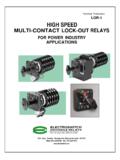
1 Proven Protection for Critical Utility Equipment and SystemsLOR/SR Self-Reset LOR/ER Electric ResetAdditional Series 24 Lock-Out Relays from ElectroswitchSLOR Serial180 King Avenue Weymouth, Massachusetts 02188 TEL: (781) 335-5200 FAX: (781) 335-4253 Lock-Out Relay Designed for today's most demanding applications, the Electroswitch 15 - Deck Lock-Out Relay: Provides 30 Normally Open (N/O) and 30 Normally Closed (N/C) contacts Trips in under 8 milliseconds Requires no special mountingPush-to-Trip Lock-Out Relay Push-to-trip Lock-Out Relays provide a safe means of tripping circuits without opening the panel or exposing maintenance personnel to risk.
2 Simplifies testing of connected circuits Eliminates the need to trip from rear of panel Allows tripping of LOR without using jumpers or trip signal Design prevents accidental tripping and ensures tripping of intended LOR Initial test is done electrically, subsequent testing can be done manually Trip button is easily accessed via a hole drilled in the panelLock-Out Relays (LORs) are designed to protect equipment and personnel in critical utility applications. In an emergency, LOR performance can mean the difference between a routine outage and the destruction of vital equipment. Proven in thousands of applications, Electroswitch Lock-Out Relays are the industry standard for safety and reliability.
3 With Electroswitch Lock-Out Relays, there s NEVER A DOUBT!Series 24 15 - Deck LORS eries 24 Push - to - Trip LORELECTROSWITCHLORS eries 24 Lock-Out RelaysNEW!Series 24 Lock-Out Relays High Quality Designed and manufactured to the highest standards in the industry Qualified to UL, CSA ANSI/IEEE ANSI/IEEE Versatility 9 Different trip coils to choose from Up to 30 N/O and 30 N/C contacts in one standard LOR Available with electric reset capability Available with built-in coil monitoring and fault signal detection/indication High-Speed Transition times of less than 8 milliseconds (1 2 cycle)
4 Are standard Availability Virtually all Series 24 Manual Reset LORs are available from stock for immediate delivery Most popular Electric Reset LORs (LOR/ERs) are also available from stockService Electroswitch Customer Service and Application Specialists can help you with product selection and application. Let us put over 50 years of know - how to work for you!ELECTROSWITCH180 King Avenue Weymouth, Massachusetts 02188 TEL: (781) 335-5200 FAX: (781) 335-4253 This publication supersedes all previous editions. Specifications subject to change at the discretion of Electroswitch .
5 L DS1-LOR 2016 Electroswitch Trip Coil Voltage DataVoltage RangeNominal VoltageThreshold VoltageOperating RangeA24 VDC6 VDC10 - 40 VDCB24 VDC9 VDC18 - 50 VDCC48 VDC12 VDC24 - 70 VDCD125 VDC120 VAC16 VDC 20 VAC30 - 140 VDC30 - 140 VACE125 VDC23 VDC45 - 140 VDCF250 VDC240 VAC33 VDC 40 VAC70 - 280 VDC60 - 280 VACG125 VDC70 VDC90 - 140 VDCH250 VDC140 VDC180 - 280 VDCK125 VDC16 VDC100 - 150 VDCD epth Behind Panel (inches)Number of DecksManual Reset LORHigh-Speed TripLOR/ERLOR/ER and Instant LOR/SR Time DelayReset Continuous Ratings: 30 A 600 VMaking Ability for CB Coils: 95 A 125 VDCUL Interrupt Ratings: 20 A 120 VAC, 15 A 240 VAC, 6 A 600 VAC, 3 A 125 VDC, 1A 250 VDCO verload Current (50 Ops): 95 A 120 VAC, 65 A 240 VAC, 35 A 600 VACC ontact Resistance.
6 01 Ohms MaximumElectronicBaud Rate: 9600 Std; 1200, 4800, 19200 SelectableTransient Protection: Meets IEEE and IEC 61000 - 4 - 4 Self - Reset Time: Optional, Programmable, to 60 Sec. MechanicalDecks 1-10, 12, 15 Std. Consult Factory for OptionsContacts 2 N/O and 2 N/C Per DeckAction 45 Mounting Panel Mount, 3 Hole Mounting,Panel Thickness 3 16" Max. Standard Consult Factory for OptionsRotary Contacts Double -Wiping Silver Overlay Phosphor - bronzeStationary Contacts Silver Inlay in Brass, Silver Plated with Integral Screw Type TerminalsConstruction Contacts Enclosed in Molded Phenolic Insulators Voltage RangeCD FNominalVoltage48 VDC125 VDC250 VDCCoil Circuit DC Ohms @ (Amps) at Rated Circuit DC Ohms @ (Amps)
7 At Rated CoilReset Coil and ElectronicsFor additional trip coil options, consult factory or see LOR-1 Tech Pub on 24 Lock-Out Relays Continuously lit left LED indicates LOR is in a ready state Continuously lit Right LED indicates presence of trip signal to warn against resetting into a fault Eliminates the need for pilot lights and expensive inter wiring, and reduces panel spaceSpecificationsOptional Lighted Nameplat