Transcription of LOR-1 HIGH SPEED - Electroswitch
1 Technical Publication LOR-1 high SPEED MULTI-CONTACT LOCK-OUT RELAYS FOR POWER INDUSTRY APPLICATIONS Electroswitch SWITCHES & RELAYS UNIT OF ELECTRO SWITCH CORP. 1 high SPEED MULTI-CONTACT LOCK-OUT RELAYS FOR POWER INDUSTRY APPLICATIONS Electroswitch Weymouth, Massachusetts ABSTRACT The Series 24 Lock-out Relays are high - SPEED (as low as eight milliseconds) control relays used primarily as auxiliary relays in applications requiring many contacts (up to 48). The LOR is an electric-trip and manual-reset device. The LOR/ER is an electric-trip and either manual or electric-reset.
2 The LOR/SR is an electric- trip and self-reset device. All units have mechanical position indicator targets. They are qualified to ESC-STD-1000, which includes aging and seismic vibration requirements to ANSI/IEEE 323-1984 and ANSI/IEEE-344-1987 for class IE uses in nuclear power generating stations. The testing also satisfies ANSI/IEEE and ANSI/IEEE INTRODUCTION Lock-out Relays of various types are often used in the electrical power industry. These auxiliary relays are electric-trip, manual or electric-reset control relays for the purpose of tripping and locking out circuit breakers or other devices automatically when a fault or other pre-determined condition exists.
3 Lock-out-relays are generally used in conjunction with protective relays to protect transformers, buses, and rotating machinery in various electrical systems. Fig. 1. Series 24 LOR Manual-reset Lock-out Relay _ Initial Release September 15, 1977 Revised January 3, 1980 Added LOR/SR February 1, 1983 Revised March 15, 1985 Revised April 15, 1987 Revised June 1, 1991 Revised February 15, 1993 Revised February 10, 1994 Revised September 1, 2012 Lock-out Relay applications often require ten or more and contacts.
4 The relays can be used to change sequences such as shutting down a faulty pump and then initiating the action to start-up a standby pump or bypassing a faulty circuit by opening and closing breakers. Lock-out-relays are normally latched in the RESET position and trip-out to a TRIP position when commanded. There are then manual-reset, electric-reset, and self- reset versions to get back to the RESET position. Fig. 2. Series 24 LOR/ER Electric-reset Lock-out Relay and LOR/SR Self-reset Lock-out Relay high - SPEED , rugged, multi-contact units are needed.
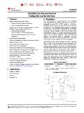
5 This paper describes a family of Lock-out relays with up to 48 contacts that operate as quickly as eight milli-seconds and are seismic shockproof. BASIC CIRCUIT OPERATION The control of the Lock-out Relays for operation as a relay requires no special wiring. They only require a contact (Sl) to command the LOR to TRIP and the Electric-reset LOR/ER needs an additional contact (S2) to initiate the command for RESET. The choice of Sl should take in consideration the burden data of trip coil, LOR/T, since Sl will "make" this current.
6 This circuit is self-interrupting with the LOR contacts so Sl need not be concerned with the "break" of the TRIP circuit. On the electric-reset LOR, S2 needs to make only the K1 relay circuit so the burden of the LOR/R does not affect S2. Any pilot duty device is acceptable for both S1 and S2. 2 Manual-reset LOR Circuit Fig. 3. Manual-reset LOR Control Circuit Schematic (shown in RESET position) The standard station control bus voltage is used. The LOR, as shown, is in the RESET position.
7 The LOR/T coil form represents the linear solenoid that releases the latch that locks the LOR in the RESET. The mechanical design is described later under THE ELECTRO-MECHANICAL DRIVE. The LOR contacts shown are normally closed in the reset position. They are within the LOR control package. G and B are tie points to connect the LOR to the control circuit. C and F are internal connection points shown for information. To command the Lock-out Relay to TRIP, S1 is closed. This completes a circuit across the LOR trigger solenoid, which operates, causing the device to snap to the TRIP position.
8 It locks into this position and remains there indefinitely. When this happens, the LOR contacts open, thereby removing the control circuit from the bus. The unit will stay locked-out in the TRIP position until manually reset. S1 may be an auxiliary contact from a breaker, a protective relay, or from another auxiliary device like a relay. The condition of the Lock-out Relay is visible by the handle location and a mechanical target within the nameplate (Black for RESET, Orange for TRIP) Electric-reset LOR/ER Circuit Fig.
9 4. Electric-reset LOR/ER Control Circuit Schematic (shown in the RESET position) The Electric-reset Lock-out Relay operates from the control bus voltage like the manual-reset version. The LOR/ER, as shown, is in the RESET POSITION. The LOR/T coil form is the same linear solenoid that is used in the manual-reset LOR, and controls the latch that locks the LOR/ER in the RESET position. The LOR/R coil form represents the rotary solenoid that is used to reset the LOR/ER electrically. Kl is a relay used to control the rotary solenoid.
10 This enables S2 to be a low level contact. It controls only the Kl relay coil. The Kl contact operates the high current rotary solenoid. TB1, TB2, and TB3 are terminal block connections, and F and H are LOR tie points all are for connection to the control bus. G, B, and TB4 are internal tie points shown for information only. The command of the LOR/ER to the TRIP position is the same as with the manual- reset LOR which was previously described. When tripped, the NC LOR contact in the LOR/T circuit opens removing LOR/T solenoid from the circuit.