Transcription of Solid-State Circuit Breakers For Medium Voltage …
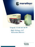
1 Solid-State Circuit Breakers For Medium Voltage DC Power M. Kempkes, I. Roth, M. Gaudreau Diversified Technologies, Inc. 35 Wiggins Ave., Bedford MA USA 01730. Abstract - How can the large power needs of future electric ships for propulsion, radar, and weapons systems be met given the prohibitive size and weight of the required number of standard 60 Hz AC generators and transformers? A solution may lie in a rugged, efficient, and compact Solid-State , 10-20 kV Medium Voltage DC. (MVDC) Circuit breaker (Figure 1). In this paper, Diversified Technologies, Inc. will describe the architecture of a Medium Voltage DC (MVDC) Circuit breaker . The Solid-State , 10 - 20 kV class breaker is a breakthrough that establishes the viability of MVDC Figure 1.
2 Conceptual drawing of a Solid-State Circuit breaker power distribution. It delivers extremely fast fault comprised of two 10 kV, 8 MW interrupters. Chassis barrier (not interruption, low peak currents, flexible and shown) measures 32 by 32 by 42 high. The entire breaker is on a programmable coordination, and mechanical isolation; horizontal drawout chassis which is disconnected or reconnected to the keys to reliable and safe operation. the buswork by the isolated high-current bus connectors. I. INTRODUCTION The same class of switches also enables high The distribution of power via MVDC links is under frequency, high- Voltage switching power converters serious consideration by power system designers for that are rugged, efficient, and compact.
3 Several reasons. First, Naval vessels must power II. Solid-State HIGH Voltage SWITCHING. propulsion, radar, and weapons systems, all of which require a DC input. However, the cumulative size and DTI's high- Voltage , Solid-State switches are series weight of the necessary number of standard 60 Hz AC arrays of semiconductor devices operating as a single generators and transformers is undesirable. Second, switch. Although the concept is simple, its execution future electrical power requirements are expected to requires careful synchronization of gate controls and support power converters capable of integrating a range snubbing of stray energy in order to ensure reliable of alternative sources and storage systems, including operation and long life of the switch.
4 These arrays can wind power, solar power, battery storage, and be constructed from several types of semiconductor flywheels, with a range of voltages, frequencies, and devices. The Insulated Gate Bipolar Transistor (IGBT). power levels. DC links are ideal for this integration, but is often the best choice, because of its wide commercial cannot be safely deployed without effective DC Circuit availability, ruggedness, speed, and low power Breakers . Ultimately, the flexibility of DC power requirement to run the gate drive. However, for very distribution systems can enhance the capabilities of high power applications (> 10 MW), the Integrated both commercial and Naval power systems. Gate Commutated Thyristor (IGCT) is desirable because of its low conduction loss.
5 In the future, this In MVDC distribution, a central MVDC bus same high Voltage technology can be used with SiC or transmitting 10 15 kV DC supplies power from one or GaN devices as they become available (and affordable), more sources to the various system loads. Within each providing even lower conduction losses, and wider zone, power converters (DC-AC and DC-DC) locally ranges of operating temperature, eliminating the need condition the power. The wide variety of loads in an all- for active cooling. electric ship require advanced Circuit Breakers /. switchgear and power converter modules that are A. Fast Fault Interruption capable of meeting the emerging standards for MVDC Solid-State , high- Voltage switching enables dramatic power.
6 Advances in Circuit breaker performance, yielding improved system reliability and safety. Because a solid- Solid-State Circuit Breakers are a key enabling state switch can interrupt the full current in technology for MVDC power distribution since they microsecond timescales, local fault protection can be can interrupt current under full load, on microsecond provided completely through the control system of the timescales, resulting in fault currents only a few times switch itself, without the need for external fault the nominal load current. Unfortunately, the detection. deployment of MVDC power has been hindered by the lack of suitable DC Circuit Breakers and high- Voltage Figure 2 shows waveforms from a 100 kV opening switches.
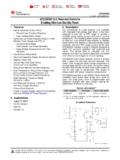
7 These requirements can now be met using switch which responds quickly enough to limit the fault fast, Solid-State , high Voltage opening switches. current (350 A) to less than twice the nominal maximum load current (200 A). The fault protection +00. t (s). 0 5 10 15 20. I (relative). Figure 4. Conceptual time-current limits for two Solid-State Circuit Breakers . The blue curve has twice the current capability as the red curve. Note that a Solid-State breaker can open in 1 s. The Figure 2. Typical DTI switch response to a fault. Ch1 Pulse Breakers can be programmed to open with a time-current profile Command; Ch2 Load Voltage (short- Circuit ); Ch3 Load current (100 less than or equal to the maximum interrupter current.)
8 A/div); Ch4 Fault (trips at 200 A); Time 1 s/div. capability of the switch is dramatically demonstrated by system with a total system inductance of 1 mH. shorting a #40 AWG wire directly across the load Figure 4, in contrast, shows curves for the maximum without destroying the test wire. It is this ultra-fast and current that two coordinated Solid-State switches are ultra-safe opening capability that provides the basis for programmed to carry. The current rise for a Solid-State the MVDC Solid-State Circuit breaker . switch into this same load would only be 10 A, with an B. Solid-State vs. Mechanical Switches opening time of 1 s. The small fault current and fast opening time for a Solid-State switch means that, unlike Fast Solid-State opening switches are an enabling the system with a mechanical switch, there is minimal technology for DC power distribution, since these impact to the load from a fault the fault will not be devices interrupt current without forming an arc and allowed to reach damaging energy levels.
9 Solid-State therefore, do not require Voltage reversal. The switches can also be programmed to open at arbitrary differences between a Solid-State switch and a currents, up to their maximum rating. If these two mechanical switch can be seen by comparing their switches ( Circuit Breakers ) are in series, the switch respective time-current plots. corresponding to the red curve will always open sooner The horizontal asymptotes of the inverse-time curves than the one represented by the blue curve. in Figure 3 indicate that mechanical switches cannot III. breaker LAYOUT. open in less than a few milliseconds. This means that the current into a short- Circuit fault will rise to very for A simplified block diagram of a Solid-State Circuit a mechanical switch would rise to 10 kA for a 10 kV breaker is shown in Figure 5.
10 The Solid-State current interrupter is comprised of a series string of Solid-State devices to safely handle the DC bus Voltage . A fast coordinated inverse-time controller provides the gate drive signal for the switches in the interrupter which synchronously open and close. The fast inverse time controller receives commands from either a manual input, from other Breakers in the network, or from fast sensors that detect local fault currents. The inverse-time controller provides inverse trip time control for overcurrent states , and a fast instantaneous trip if the overcurrent limit is reached, as shown in the coordination curve in Figure 4. These operational parameters can be adjusted for each breaker depending on its location in the network, providing orderly, sequenced response to fault conditions.