Transcription of New Transport Network Architectures for 5G RAN - Fujitsu
1 Independent market research and competitive analysis of next-generation business and technology solutions for service providers and vendors New Transport Network Architectures for 5G RAN A Heavy Reading white paper produced for Fujitsu AUTHOR: GABRIEL BROWN, PRINCIPAL ANALYST, HEAVY READING HEAVY READING | Fujitsu | NEW Transport Network Architectures FOR 5G RAN 2 5G RAN NEW REQUIREMENTS; NEW Architectures Advanced operators are preparing for rapid deployment of 5G networks. Their aim is to evolve today's mobile broadband services, through lower unit costs and improved end-user perfor-mance, and to address new business segments using 5G system capabilities. To achieve this, operators are designing Network Architectures that will scale to device and traffic densities far beyond what is commonplace in LTE networks today and meet the latency and reliability re-quirements of demanding new service types.
2 This is critical preparation for the 5G super-cycle that will enable operators to extend their reach into diverse markets over the next 10 years. An essential part of the new design is the Transport Network that provides connectivity be-tween radio sites, edge data centers and cloud applications. This white paper investigates this new Transport architecture and the role that packet-based connectivity fabrics play in the performance of the 5G RAN itself and on revenue-generating end-user services. Because 5G will be introduced into large, well-optimized and commercially productive LTE networks, integration into existing environments is important; therefore, this paper also discusses the importance of integrated 4G/5G Transport . The paper argues that 5G RAN Transport and connectivity is more than a necessary cost. For Network operators, it is an investment in critical assets that will generate unique advantages in the way customers experience, and interact with, services.
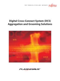
3 It is an architecture for the long-term development of the 5G service offer. Market Outlook & Deployment Strategies The first specifications for the 5G system, covering radio and core, are now available. This gives the industry the confidence to accelerate commercial launch, and several high-profile operators have stated that they expect to launch commercially in 2018 and 2019; we then expect many operators to follow in 2020 and 2021. Within five years of launch, it is plausible, in advanced markets, that 50 percent of an operator's subscribers will be 5G customers. Figure 1 shows a timeline for commercial launch, coverage expansion and operation at scale. The first commercial launch to be announced is Verizon's 5G Home service, a fixed wireless broadband service that will go live in October 2018. Figure 1: Timeline for 5G Deployment at Scale Source: Heavy Reading HEAVY READING | Fujitsu | NEW Transport Network Architectures FOR 5G RAN 3 5G RAN architecture The 3 GPP 5G RAN architecture specified in Release 15 and known as NG-RAN introduces new terminology, interfaces and functional modules.
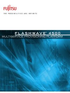
4 The NG-RAN consists of a set of radio base stations (known as gNBs) connected to the 5G core Network (5GC) and to each other. The gNB incorporates three main functional modules: the Centralized Unit (CU), the Distrib-uted Unit (DU), and the Radio Unit (RU), which can be deployed in multiple combinations. The primary new interface is the F1 interface between DU and CU This are expected to be interoperable across vendors. Standardization of a further lower-layer interface between DU and RU is under consideration, but progress is likely to occur outside the 3 GPP in the first instance. The CU can be further disaggregated into the CU user plane (CU-UP) and CU control plane (CU-CP), both of which connect to the DU over F1-U and F1-C interfaces re-spectively. This new 5G RAN architecture is described in 3 GPP TS Figure 2: Location Flexibility for 5G RAN Functional Units Source: NGMN, 2018 As with all 3 GPP standards, NG-RAN is a logical architecture that can be implemented and deployed in different ways, according to an operator's requirements and preferences.
5 As shown to the right of Figure 2, the base station can be deployed as a monolithic unit de-ployed at the cell site, as in classic cellular networks, or split between the CU, DU and RU. The CU-DU interface is a higher-layer split (HLS), which is more tolerant to delay. The DU-RU interface, which is not yet standardized, is a lower-layer split (LLS), which is more latency-sensitive and demanding on bandwidth, but may offer improved radio performance across a coverage area due to coordination gain. CUs, DUs and RUs can be deployed at locations such as cell sites (including towers, rooftops and associated cabinets and shelters), Transport aggregation sites and "edge sites" ( , central offices or local exchange sites). Which 5G RAN Deployment architecture ? The choice between lower-layer and higher-layer splits is a critical decision in NG-RAN archi-tecture. The challenge is that the trade-offs are not always clear-cut, and it can be hard to HEAVY READING | Fujitsu | NEW Transport Network Architectures FOR 5G RAN 4 determine which model will be economically optimal for each carrier.
6 Moreover, it may make sense to use different models for different regions for example, rural coverage versus urban capacity. There will also be variation for different use cases for example, an ultra-low-latency factory automation Network would require DU/CU close to, or inte-grated with, the RU. Figure 3 shows the high-level trade-off between coordination gain from centralization and the latency and bandwidth requirements in the Transport (front-haul) Network . Figure 3: Coordination Gain & Functional Splits Source: Heavy Reading It is not straightforward to determine the optimal RAN topology and associated operating model. Usage patterns, device capabilities, operating costs, RF strategy and the existing Network footprint and capabilities are all influential on the decision. The Transport Network is especially important because it provides connectivity between the NG-RAN functional modules and therefore determines, in the first instance, which deployment topologies are possible, and then, which are cost-effective.
7 Figure 4 shows the primary functional elements of the 5G RAN (RU, DU and CU) and how they are logically mapped to the Transport Network . Figure 4: Mapping 5G RAN to Transport Network Source: Heavy Reading A lower-layer split between the DU and RU is demanding in terms of bandwidth, latency and packet loss, and to deploy a DU at a distance from the cell site typically requires the operator to invest in fronthaul fiber infrastructure. A higher-layer RAN split, with DUs deployed at the HEAVY READING | Fujitsu | NEW Transport Network Architectures FOR 5G RAN 5 cell site, is more tolerant in terms of Transport performance, but perhaps offers less coordi-nation gain and, potentially, higher opex in the longer run. And RAN technology decisions alone do not determine the architecture : If the operator wants to support ultra-low-latency and ultra-reliable services, then the Network will need to be designed accordingly for example, for certain applications the radio compute ( the DU/CU) may need to be deployed at the cell site, or on-premises, to meet latency and avail-ability targets of the end-user service.
8 The 5G RAN deployment architecture is therefore codependent on RAN design, the Transport Network and end-user services. Mapping Functional Modules to the Physical Network Decisions on where to place 5G RAN and core Network functions depend on service require-ments and the Transport and compute capabilities deployed in the Network . Figures 6, 7 and 8 show example deployment topologies. Macro cells and small cells connect to external net-works through user plane functions (UPFs) in the 5G core via a series of Transport aggregation sites. These aggregation sites decrease in number toward the core, with a corresponding increase in Transport capacity for example, for a Network with 1,000 Tier 1 sites, there might be 100 Tier 2 sites and 10 Tier 3 sites. Where specifically RAN and core functions are deployed will vary between, and within, oper-ators. End-to-end Network latency probably the critical determinant.
9 The Next Generation Mobile Network (NGMN) Alliance guidelines for one-way latency from the cell site to a Tier 1, Tier 2 and Tier 3 aggregation site are ms, ms and ms respectively. Therefore, for a mobile broadband service with tolerance for a 10 ms roundtrip delay, the deployment model shown in Figure 5 may be optimal. In this case, the RAN CU and the core UPF are colocated at the Tier 2 site ( , a central office), while the DU may be distrib-uted to a Tier 1 aggregation site or to the cell site itself (or be located close by, in a cabinet or shelter). Figure 5: Deployment Topology for <10 ms Latency ( , Mobile Broadband) Source: NGMN HEAVY READING | Fujitsu | NEW Transport Network Architectures FOR 5G RAN 6 In Figure 6 the UPF is deployed closer to the edge at the Tier 1 site, to give around 5 ms roundtrip latency. This edge facility may also host a multi-access edge computing (MEC) platform to host and run latency-sensitive applications.
10 Figure 6: Deployment Topology for <5 ms Latency ( , AGVs) Source: NGMN In Figure 7 the CU and DU are colocated with the RU, or even integrated into a single unit, at the cell site. Because very low latency is required, the core Network (UPF) and MEC server may also be deployed at the cell site to enable applications to run locally. An example service may a next-gen factory automation using 5G for robotic motion control in an industrial production line. Figure 7: Ultra-Low-Latency (1 ms) Deployment ( , Industrial Automation) Source: NGMN HEAVY READING | Fujitsu | NEW Transport Network Architectures FOR 5G RAN 7 AN OPEN X-HAUL Transport Network The new 5G RAN and end-user services requirements drive the need for a new Transport Network . While many 4G assets can be reused, it will not be sufficient to overlay 5G on a 4G backhaul architecture , and even where an operator has deployed an advanced C-RAN archi-tecture, new investment is required to meet 5G requirements.