Transcription of Obstetrical Care - Frank's Hospital Workshop
1 FETAL MONITORINGINSTRUCTIONS FOR USEO bstetrical CareAvalon CTSC ordless Fetal Transducer SystemM2720 ASPrinted in Germany 08/04*M2720-9001C*Part Number M2720-9001C4512 610 04471 Avalon CTSC ordless Fetal Transducer SystemM2720AM2720-9001 CPrinted in GermanyAugust 2004 INSTRUCTIONS FOR USEiiiiiContents1 Introduction1 Who This Book is For1 Intended Use2 Warnings, Cautions and Important Information22 Installation3 When is the Avalon CTS Customer Installable?3 When Are Special Configurations Needed?3 Installation Checklist4 Checking the Shipment 4 Setting Up the System for the First Time5 Connecting and Assembling the Standard Antenna 5 Mounting Solutions6 Connecting the Base Station to a Fetal Monitor7 How and When to Carry Out Tests8 Safety Tests8 Connecting the Base Station to AC Mains9 System Test9 What is a Medical Electrical System?
2 9 General Requirements for a System9 System Example103 Basic Operation11 Base Station11 Slot Arrangement13 Transducers14 MECG and DECG Transducers154 Monitoring a Patient17 What You Can Monitor 17 Flexible Monitoring17 Radiated Transmission Power17 Getting Ready to Monitor18 Applying a Transducer18 Using Transducers19 Changing Between US and DECG Monitoring19 Monitoring Twins20 After Monitoring20 Selecting Stand-by Mode20ivUnderwater Monitoring 21 About RF Signal Quality 21 Other Monitoring Considerations225 Transducer Behavior23 Docking Transducers23 Removing a Transducer from the Base Station24 Switching Off Transducers246 Troubleshooting25 Warnings and What To Do About Them 25 Error Handling27 Error Messages27 Displaying the Error Messages28 Solving General Problems29 Blocked Slots 317 care and Cleaning33 General Points33 Cleaning34 Disinfecting34 Sterilizing348 Maintenance35 Battery Care36 Performance Assurance36 Parameter Test36 Toco Transducer Ventilation Knob/Membrane 38 Testing Alarms 389 Accessories and Supplies39 Information on Latex39 Approved Accessories and Supplies3910 Specifications and Standards Compliance41 General41 Base Station41 Transducers42 Frequency Bands43 Availability in EU and EFTA Countries43 Frontends44 Cables45 Compatible Fetal Monitors45 Standards Compliance45 Safety 45 Electromagnetic Compatibility (EMC) 46vEMC Testing46 Reducing Electromagnetic Interference47 System Characteristics48 Electromagnetic Emissions48 Radio Requirements 48 FCC Compliance (USA only)
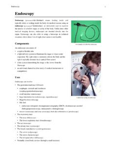
3 49 Canadian Radio Equipment Compliance (Canada Only)49 Environment49 ESU, MRI and Defibrillation50 Protective Earth51 Maximum Input/Output Voltages51 Statement of Conformity5111 Glossary5312 Advanced Configuration55 Bed Label55 Theft Protection Level 56 Theft Protection Alert Volume 56 Audible Alert Volume 57 Key Click Volume 58 Acoustical Alarm Default5813 Disposal61vi111 IntroductionWho This Book is ForThis book describes how to set up and use the Avalon CTS Cordless Fetal Transducer System with a fetal monitor. You should be familiar with using medical devices and with standard fetal monitoring procedures, such as fastening belts and placing transducers. For details of installation procedures and who should carry them out, see Installation starting on page information you need to use your fetal monitor and transducers is in the fetal monitor s Instructions for Use.
4 Ensure that you read and understand these instructions. Refer also to the instructions that accompany any accessories and exact appearance of your system, regarding details of product livery, may vary slightly from that information on how to service the system, refer to the Service IntroductionIntended Use2 Intended UseWhen connected to a compatible fetal monitor, the Avalon CTS Cordless Fetal Transducer System (M2720A) lets you perform continuous, cordless patient monitoring in the antepartum period and during labor and can continuously monitor the fetal heart rate (FHR) non-invasively using ultrasound, or invasively by direct electrocardiogram (DECG), and the uterine activity using an external Toco fetal parameters are measured and transmitted continuously via radio frequency from the transducer to the base station, eliminating the need for patient cables.
5 The fetal monitor, connected to the base station, displays and records the the transducers are watertight. You can continuously monitor patients in a bath or shower using the Toco (M2725A) and the Ultrasound (M2726A) system should only be used by, or under the direct supervision of, a licensed physician or other health care practitioner who is trained in the use of FHR monitors and in the interpretation of FHR , Cautions and Important InformationWARNINGA warning alerts you to a potential serious outcome, adverse event or safety hazard. Failure to observe a warning may result in death or serious injury to the user or caution alerts you to circumstances where special care is necessary for the safe and effective use of the product. Failure to observe a caution may result in minor or moderate personal injury, damage to the product or other property, and possibly in a remote risk of more serious injury.
6 Copyright 1995-2004 Koninklijke Philips Electronics All Rights your system, this sign indicates that there is detailed information in this book which you must read before proceeding with your this book, graphical symbols (indicators or elements of the base station or transducer displays) depicted in this way indicate that they are chapter describes how to install the Avalon is the Avalon CTS Customer Installable?The Avalon CTS is intended to be customer installable under the following conditions: The system in its standard configuration is an out-of-the-box , standalone system, delivered with automatic frequency allocation, and is intended to be used with the standard antenna supplied, giving a line-of-sight operating range up to 100m/300ft. There are less than ten stand-alone systems in the institution.
7 Connection to an antenna system is not planned. No other telemetry devices are used in the institution that can influence, or be influenced by, the Avalon CTS. There are no other sources of RF interference that influence the operation of the Avalon CTS. There are no country-specific regulations requiring special should be carried out by qualified technical you need to mount the Avalon CTS, or use the antenna extension mounting kit (M1361A Option 1AA), see the Service Guide for further Are Special Configurations Needed?If one or more of the conditions above are not met, you need a special configuration of the Avalon CTS. For instance, you may need to: Set fixed frequencies when there are other telemetry systems installed in the same institution (always applies to Japan).
8 This configuration should be carried out by qualified service personnel, either from the Hospital s biomedical department, or from Philips (see the Service Guide). Connect the Avalon CTS to an antenna system because the standard antenna is not sufficient to cover the area intended for cordless monitoring. Site preparation, antenna system design (including guidelines for mixed telemetry equipment installations), and installation should be carried out by qualified service personnel from InstallationInstallation Checklist4 Installation ChecklistUse this checklist for customer installable configurations. Refer to the Service Guide and/or contact Philips Support for installation requirements for all other delivery the Shipment Unpack the system carefully. Retain the packing materials in case you need to return the system to Philips or transport your system.
9 Use this table to check your delivery. Inspect all system components, accessories and supplies for damage before setting up your Box when Task Done1 Perform initial inspection of delivery, unpack and check the shipment(see page 4) 2 Connect and assemble the antenna (see page 5) 3 Mount the monitor as appropriate for your installation(see page 6) 4 Connect the base station to the fetal monitor (see page 7) 5 Perform Safety Tests (see page 8) 6 Connect the base station to AC mains using the supplied power cord (see page 9) 7 Perform System Test as necessary (see System Test on page 9) 8 Perform Parameter Test (see Parameter Test on page 36) System Components, Accessories and SuppliesQuantityBase station1 Ultrasound transducer, cordless, waterproof1*Ultrasound transmission gel1 bottle*Transducer belts, waterproof, reusable3*Toco transducer, cordless, waterproof1*ECG transducer1 (optional)Antenna with rectangular BNC connector1 Interface cable, for connection to fetal monitor1 Power cable1 Service cable1 Instructions for Use1 Documentation CD-ROM (Instructions for Use, Service Guide, and Service Support Tool)
10 1* Delivered quantity depends on which option you Up the System for the First Time2 Installation5 Setting Up the System for the First TimeConnecting and Assembling the Standard Antenna 1 Line up the nodules on the right angle connector with the spaces on the antenna in and the antenna1 to the base station by turning the connector collar (A) at the base of the antenna so that the two spaces (B) are positioned at the top and bottom. These fit over the two notches (C) on the base station antenna the antenna onto the input socket at the rear of the base the connector collar (A) clockwise until it stops. The antenna should be positioned vertically to ensure the best operating AC mains Terminal. See Symbols on the System on page Socket. mm stereo jack for connecting the Service Support Tool (service personnel only).