Transcription of OPERATING & MAINTENANCE MANUAL …
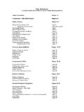
1 OPERATING & MAINTENANCE MANUAL Electrically Heated Furnace Model No.: Serial No. Copyright 2006 Cress Manufacturing Company, Inc. All Rights Reserved Cress Manufacturing Company, Inc. 4736 Convair Drive Carson City, Nevada 89706-0493, USA Phone , Fax Page 2 of 17 TABLE OF CONTENTS MANUAL Cover Page 1 Table of Contents 2 Introduction 3 General Description 4 Inspection & Installation 5 First Time Use 7 Operation 8 MAINTENANCE 11 Troubleshooting 15 Warranty 16
2 electrical Diagram 17 Appendix A - Instrumentation Manuals 18 Page 3 of 17 INTRODUCTION This MANUAL has been prepared for your CRESS FURNACE. Single chamber models are rated for 2250 F maximum intermittent temperature. For continuous operation, this furnace is rated for 2100 F maximum. Draw models are rated for 1250 F maximum intermittent and 1100 F continuous temperature. High Temperature Draws are rated for 2000 F maximum intermittent temperature and 1850 F of continuous temperature. Dual chambers: These units have a combination of a heat treating upper chamber and a drawing lower chamber. The upper chamber is rated for 2250 F maximum intermittent temperature. For continuous operation, the furnace is rated for 2100 F maximum. The lower draw chamber is rated for 1250 F maximum intermittent and 1100 F continuous temperature.
3 Some of the dual chamber furnaces may have a high temperature lower chamber; in that case, they are rated for 2000 F maximum intermittent temperature and 1850 F of continuous temperature. Before attempting to install or operate this equipment, the operator must first have READ THE ENTIRE CONTENTS OF THIS MANUAL and have become familiar with the safe operation of the equipment. Failure to do so can result in damage to the furnace equipment or even possible injury to personnel. The Instructions in this MANUAL are intended to serve as a guide to the safe and efficient use of your Cress Furnace. The information provided in the Temperature Control Manuals should be consulted for instruction how to operate the control instruments. For all your furnace spare parts, call Cress Manufacturing Company, Inc: Tel.: (775) 884-2777 Toll Free: (800) 423-4584 Or Fax: (775) 884-2991 Or e-mail: The Serial Number and Model Number of the furnace should be furnished whenever information or spare parts are requested.
4 This will aid in expediting the request at our factory. These numbers are also stamped on the Data Plate mounted on the furnace. Serial Numbers and Model Numbers of instruments will be found on the respective instruments. Page 4 of 17 GENERAL DESCRIPTION Single Chamber Furnaces may be use for hardening and process temperatures of up to 2250 F. Single Chamber Draw Furnaces: These furnaces come equipped with a recirculation fan, which helps to achieve an even temperature through the chamber. These furnaces are suitable for hardening and other heat treating metal processing applications that do not exceed 1250 F or 2000 F if it has a high temperature fan. The Dual Chamber Furnace is designed to provide two separately controlled heating chambers within a minimum amount of floor space. The upper chamber is typically rated for temperatures of up to 2250 F: The lower chamber is rated for temperatures of up to 1250 F unless the furnace is equipped with a high temperature fan.
5 If that is the case, then the maximum temperature will be 2000 F. The dual chamber furnaces are capable of performing two separate heat treating functions at the same time. The high temperature upper chamber may be used for hardening. The lower chamber is a separate furnace that may be used for tempering or drawing. While a hardening process is on going in the upper chamber; drawing or tempering of another item can be accomplished in the lower chamber. This dual chamber concept allows for immediate drawing or tempering after quench. The operator no longer has to wait for the hardening furnace to cool to a lower temperature required for drawing or tempering. During your purchase of this furnace you were given the choice of either a set-point temperature controller, or an optional programmable temperature controller. Therefore, the instrumentation purchased can vary from customer to customer. For electrical safety, the chamber door has an electrical limit switch.
6 If the chamber door is opened, it will activate the limit switch to interrupt power supply to the heating chamber, disabling the elements from heating. Some furnaces are not supplied with a power cord and must be hard wired to your electrical service. The furnace must also be grounded electrically. All electrical work needs to be done in compliance with Building Code standards. Page 5 of 17 WARNINGS & PRECAUTIONS electrical voltage is dangerous! Do not work on the furnace while electrical power is turned ON. Consider all electrical leads to be energized until positively proven they are de-energized. Be certain that your electrical wiring, receptacles, switches, circuit breakers, or fuses are in good condition and are adequate for this furnace. To prevent accidental shock during loading or unloading of the heating chamber, the power switch must be in the "OFF" position. To prevent burns on hands or arms, protective gloves should be worn while loading or unloading a "HOT" chamber.
7 If heat is excessive, a face shield should also be worn. Keep face and eyes away from the opening of a "HOT" chamber. Opening chamber door while chamber is at high temperature or allowing the door to "SLAM" during opening or closing may cause thermal shock and cause damage to the insulating brick. Combustible material must not be placed in, on or near the furnace. Do not set any materials, tools or liquids on top of the furnace. STEP #1 - INSPECTION Inspection: Before unpacking the furnace visually inspect each item to see if there is any freight damage. Freight Claim: If any damage to the exterior of these items is noted at this time (or to the interior of any of these items when inspected later), it is the responsibility of the receiving party to file a freight claim with the shipping company. Do not continue the installation if freight damage is found at any point of the INSTALLATION and/or OPERATION procedures. Uncrating: When taking items out of the crates, check that each item in each crate is accounted for per the packing list provided.
8 Remove all material that may be packed in the heating chamber. STEP #2 - INSTALLATION The entire furnace has been integrally wired to control panel to require a single electrical service connection. The furnace should be lifted from the side opposite the control panel (dual chamber) and supported or stabilized while moving to avoid falling. We recommend the use of a single 1,000 lbs. or more capacity forklift. There is no lifting point on the roof of the furnace and it is not recommended because of the way the furnace is built (the roof or top structure is attached only by sheet metal screws). Please verify clearances through your building doors and corridors before moving the furnace to avoid any damage to the control panel or to the furnace structure. Prior to installation, make certain that the floor beneath the furnace is level. The furnace should not be placed closer than 18" to any wall or vertical surface or under shelving or other projections.
9 If using Cress furnace stand, it must be secured to the floor using stand s mounting holes. Dual chamber furnaces must be anchor to the floor. The room in which the furnace is operated should be well ventilated. Before plugging the furnace into your outlet or connecting the furnace to a power source, be sure that the toggle switch or electrical timer is in the Page 6 of 17 "off" position. Be certain that your electrical wiring, receptacle, circuit breaker, and fuses are in good condition and adequate for the furnace before connecting. If you are not sure, consult a qualified, licensed electrician. On furnaces equipped with a power cord, the metal case is grounded by the power cord ground connection. Furnaces not equipped with cords must be grounded by a separate grounding wire of a suitable wire gauge to handle the entire amperage possible on the incoming power line. power should come from a fused disconnect switch in the immediate vicinity of the Care should be taken to keep the furnace away from flammable surfaces.
10 A good rule is to keep the furnace at least 18" or more from all vertical surfaces. Do not use the furnace under a shelf or other obstruction to the flow of air. Keep all flammable liquids out of the room with the furnace. Be sure no curtains or other material that could change position with wind or opening of a door or window can come within an unsafe distance of the furnace. If the furnace is to be used for a lost wax process, wax burnout or assaying, and its not equipped with a Cress Vent System, drill a 1" hole through the center top of the furnace chamber. WARNING: DO NOT USE FOR LOST WAX PROCESS OR ASSAYING UNLESS A VENT HOLE IS DRILLED THROUGH THE TOP OF THE FURNACE. REMOVE ALL WAX EXCEPT RESIDUE BELOW 400 F (205 C) TO PREVENT EXCESS CONCENTRATION OF CONTAMINANTS FROM DESTROYING THE ELEMENTS. STEP #3 - HEATING ELEMENT INSTALLATION The heating elements are already installed in this furnace. Therefore, all you need to do is make sure to remove any packing materials inside of the heating chamber.