Transcription of Operating and Maintenance Instructions …
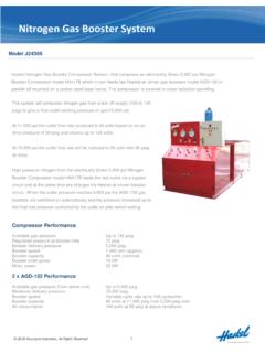
1 OM-3F Operating and Maintenance Instructions Instructions de Fonctionnement et d Entretien Betriebs- und Wartungsanleitungen Istruzioni di Prestazione e Manutenzione Instru es de Funcionamento e Manuten o Air Driven Gas Booster Compressors 5-3/4 Drive AG Series Surpresseurs d Air Pneumatique Gaz Entra nement 5-3/4 S rie AG Luftdruck Gas-Booster Druckluftzylinder Kompressoren Schalld mpfer 5-3/4 Antrieb AG Reihe Compressori Generatore a Gas Trasmissione ad Aria Serie Trasmissione AG 5-3/4 Compressores de G s Tipo Gas Booster com Comando Pneum tico S rie AG 5-3/4 Air Driven Gas Booster Compressor, 5-3/4 Drive AG Series OM-3F 1 1. Pilot Valve 2. Air Piston 3. Air Drive Barrel 4. Connecting Rod 5. Exhaust Muffler 6.
2 High Pressure Barrel 7. Pump Outlet 8. Check Valves 9. Pump Inlet 10. Cooling Jacket 11. Air Exhaust Tube 12. Pump Piston 13. Air Cycling Valve 14. Air Drive Inlet Port 15. Upper & Lower Caps 1. Robinets Pilotes 2. Piston a Air 3. Colonne du Mecanisme a Entrainement d Air 4. Axe de Tirette 5. Silencieux d Echappement 6. Colonne a Haute Pression Igh 7. Sortie de la Pompe 8. Clapets Anti-Retour 9. Entree de la Pompe 10. Enveloppe de Refroidissement 11. Tube d echappement d Air 12. Piston de la Pompe 13. Vanne de Cyclage d Air 14. Orifice d entree du Mecanisme a Entrainement d Air 15. Capuchons Superieur et Inferieur 1. Pilotventil 2. Doppelter Druckluftkopf Doppelt Wirkend Oder 2-Stufig 3.
3 Druckluftzylinder 4. Verbindungsstange 5. Schalld mpfer 6. Hochdruckzylinder 7. Pumpenausgang 8. R ckschlagventile 9. Pumpeneingang 10. K hlmantel 11. Abluftleitung 12. Pumpenkolben 13. Lufttaktventil 14. 15. Obere/Untere Kappen 1. Valvola Pilota 2. Pistone Ad Aria 3. Barrel A Trasmissione Ad Aria 4. Collegamento All asta 5..Scarico Marmitta 6. Barrel Ad Alta Pressione 7. Uscita Pompa 8. Valvole Di Controllo 9. Ingresso Pompa 10. Camicia Di Raffredd 11. Tubo Scarico Aria 12. Pistone Pompa 13. Valvola Circolazione Aria 14. Porta Entrata Trasmiss Aria 15. Coperchi Sup. Pi Bassi 1. V lvula Piloto 2. Pist o Pneum tico 3. Cilindro Pneum tico 4.
4 Barra de Liga o 5. Silencioso 6. Cilindro de Alta Press o 7. Sa da da Bomba 8. V lvulas de Reten o 9. Entrada da Bomba 10. Camisa Refrigera o 11. Tubo de Escape de Ar 12. Pist o 13. V lvula de Circula o de Ar 14. Entrada do Comando Pneum tico 15. Tampas Inferior e Superior Air Driven Gas Booster Compressor, 5-3/4 Drive AG Series OM-3F 2 Introduction The Haskel Oil free gas booster compressor is an air driven, non-lubricated, reciprocating piston type gas compressor available in single acting single stage, double acting single stage, and two stage configurations. Individual models may also be used in series for multiple staging. The model number is the approximate ratio of the air drive piston(s) area to the gas piston(s) area.
5 CAUTION: High pressure gas can be dangerous if improperly handled. Description General The air drive piston(s) in all models are automatically cycled by a non-detented, unbalanced air valve spool that is alternately pressurized and vented by the pilot air system. This drive is directly connected to the booster section piston(s) which are designed to run dry without lubrication to supply gas free of hydrocarbon contamination. Exhaust air from the drive is used to cool the gas barrels and in 2 stage units, the gas intercooler. Some models depend on the cold air exhausting from the muffler slots directly against the gas barrel (without benefit of a cooling jacket). Therefore, the position of the exhaust muffler on these models should not be disturbed. Mufflers on models with cooling jackets may be relocated for noise or configuration convenience.
6 Air Drive Section Refer to detailed assembly drawing of the air drive section provided with each unit. The air drive section consists of one or more air drive piston assemblies, an unbalanced spool type cycling control valve and pilot valves (one mounted in the valve end cap and one in the opposite end cap), a flow tube to direct drive air flow from the valve end cap to the opposite end cap, and pilot tube to connect the two pilot valves, which are in series. The drive control valve operates without springs or detents and is cycled by the pilot valves alternately pressurizing and venting the large area on the inside end of this spool valve. The control valve, pilot valves and drive cylinder are lubricated with Haskel air drive grease, part no. 50866, at assembly. Occasional relube of the easily accessible control valve and pilot valves with this grease may be needed depending on the duty cycle of the installation.
7 It is recommended that only o-rings and seals of proper compounds and hardness for low friction be used in the air drive section. Haskel replacement seals are recommended. If not otherwise installed by the factory, always install a conventional bowl type shop air filter/water separator of the same or larger pipe size on the incoming air drive plumbing. Drain and maintain it regularly. Do not use an airline lubricator of any kind. Gas Section Refer to the detailed assembly drawing on the gas section(s) provided with each unit. These sheets cover the individual parts and their installation for the gas section of the individual models. Note that no lubrication of any kind is ever used on the dynamic seals of the gas pumping sections. They are designed to run dry supported on the inherent low friction properties of the seal and bearing materials.
8 The life of the gas section also depends on the cleanliness of the gas supply. Therefore, micronic filtration is suggested at the gas inlet port. If compressed air or other moisture containing gas is to be pumped, the initial dew point should be low enough to prevent saturation at booster output pressure, and if any carry over of oil from the compressed air source is evident, special coalescing type filtration may be necessary. Over the life of the moving parts, some migration of inert particles into the gas output should be expected. Therefore, a small particle filter on the high pressure line may be advisable for critical applications. COMPRESSION RATIO-VOLUMETRIC EFFICIENCY The compression ratio is the ratio of output pressure to gas supply pressure. (To calculate, use psi absolute values.)
9 The gas pumping sections are designed to have minimum unswept or clearance volume at the end of the compression stroke. On the return (suction) stroke of the piston, output pressure in the Air Driven Gas Booster Compressor, 5-3/4 Drive AG Series OM-3F 3 unswept volume expands to inlet pressure. This reduces the amount of potential fresh gas intake on the suction stroke. Volumetric efficiency therefore decreases rapidly with an increase in compression ratio until the volumetric efficiency reaches zero when the unexpelled (expanded) gas completely fills the cylinder at the end of the intake stroke. A cylinder with a 4% unswept volume will reach zero efficiency at a compression ratio of approximately 25:1. Production models of Haskel gas boosters are tested in the laboratory.
10 Results of these tests indicate that compression ratios of up to 40:1 are possible for some models under ideal conditions. However, for satisfactory operation under production conditions in industrial applications, we recommend compression ratios (per stage) of about 10:1 or less. Operation at higher ratios may not damage the gas booster but because output flow and efficiency will be low, the use should be limited to pressurizing small volumes such as pressure gauge testing, etc. COOLING Effective cooling of the gas pumping section is of paramount importance as service life of piston seals, bearings, and static seals are dependent upon proper Operating temperatures. Haskel gas boosters use the exhaust air from the driving system to cool the gas barrel (and gas intercooler on the two stage models).