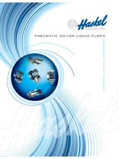
Transcription of Pressure on Demand - Haskel
1 pneumatic driven liquid PumpsPressure on DemandHigh PressureHaskel pneumatic driven liquid pumps are designed to provide a safe, reliable and economical, source of hydraulic brochure introduces our pneumatic driven liquid pump range. Visit our website at for more information or to locate a distributor. Safe pneumatic operation no heat, flame or spark risk Up to 100,000 psi (7000 bar) capability Infinitely variable cycling speed Stall feature at pre-determined Pressure to hold that Pressure without consuming power Problem-free stop/start applications Easily automated many modification and control options Suitable for most liquids and liquefied gases Alternative gas drive options sour gas, natural gas, boil off gases, nitrogen No need for air line lubrication saves costs and prevents contamination Robust, reliable, compact and easy to maintain proven design Unbalanced cycling spool provides immediate response to Pressure changes Also available in standard, or custom built power pac configurations Excellent worldwide service for spares and repairs ATEX approved CE certifiedWhy Use Haskel pneumatic driven pumps ?
2 Our pumps offer many advantages over electrically driven pumps :Applications include: Pressure testing Work holding/power clamping Jacking/lifting Valve actuator control Hydraulic cylinder actuation Press safety overload devices Roller tensioning Metering Precision lubrication and spraying Liquefied gas and Flow on DemandThis guide will help you to pre-select the pump ideally suited for your application. If you have specific questions, however, we urge you to provide Haskel with the operational details of your application. We will recommend a model and any corresponding Horsepower RatingsThe pumps are categorized on their horsepower ratings (see pages 6-7). These are approximate and peak at 100 psi (7 bar), assuming adequate drive, Pressure and volume. Peak horsepower is at about 75% nominal ratio x drive Pressure , 100:1 pump @ 100 psi air drive peaks at 100 x 100 = 10000 x psi = 7500 psi (517 bar) hydraulic and Triple Air Head PumpsPerformance can be extended for the hp pumps by stacking air pistons without changing the hydraulic piston.
3 Haskel multi-head pumps consume less air than competitive single head pumps of the same area, as only one head is pressurized on the return stroke; , on a hp pump additional heads can raise performance to 2 air head pumps are identified by the last digit 2 in the pump model number. Thus, a nominal 50:1 ratio pump with two air heads is described as a 52. Similarly, a triple air head pump is identified with a last digit 3. Thus, a 900 ratio pump with three air heads is described as a pumps automatically reciprocate on a differential piston principle. A large piston driven by relatively low Pressure drive acts directly upon a smaller hydraulic nominal ratio between piston sizes is indicated in the model coding and approximates to the maximum working Pressure . The actual ratio is about 15% above nominal so that the pump continues to cycle when drive Pressure equals nominal ratio.
4 Initially, the pump will cycle at maximum speed acting as a transfer pump to pressurize downstream. It will cycle at a slower rate as the fluid meets resistance until it stalls at maximum output Pressure . When a Pressure drop downstream occurs, it will recycle as necessary in an effort to maintain maximum Pressure . Stall Pressure is achieved when the outlet Pressure rises and offers more resistance to the reciprocating differential piston assembly. The piston assembly then stalls when the forces balance, when drive Pressure x drive piston area equals outlet (stall) Pressure x driven hydraulic plunger area. The pump design is sensitive to very small Pressure drops due to the low frictional resistance of the large diameter drive piston and hydraulic piston Drive Head PumpDouble Air Head PumpTriple Air Head PumpNominal Ratio * (2) Indicates Double Drive Piston** (3) Indicates Triple Drive sq in (4 sq cm)Therefore, actual ratio = 40:1 Nominal Ratio = 35 sq in (167 sq cm)Area.
5 65 sq in (4 sq cm)Therefore, actual ratio = 79:1 Nominal Ratio = 72:1*Area sq in (163 sq cm)Area sq in (167 sq cm)Area .65 sq in (4 sq cm)Therefore, actual ratio = 118:1 Nominal Ratio = 103:1**Area sq in (163 sq cm)Area sq in (163 sq cm)Area sq in (167 sq cm)Anatomy of a pneumatic driven Pump 1. Drive SectionThe piston, complete with O ring seal, operates in an epoxy filled, fiberglass wound barrel, the diameter of which is constant throughout a given series of pumps . Drive media forces the piston down on the compression stroke and raises it on the suction stroke (M series have a spring return). The piston is pre-lubricated during assembly and therefore no air line lubricator is Hydraulic Section/Check ValvesThe drive piston is linked and connected to the hydraulic plunger/piston in the hydraulic section. Outlet flow and Pressure are determined by the area of the hydraulic piston head, its nominal ratio with the drive piston head, and drive Pressure .
6 On the down stroke, liquid in the hydraulic section is forced under compression through the outlet check valve. Fresh liquid is induced via the inlet check valve on the return stroke. These check valves control the flow of liquid through the hydraulic section. They are spring-loaded and have a very low cracking Pressure , allowing maximum opening on the induction stroke. The Pressure of hydraulic fluid on the down stroke closes the inlet check valve and acts against the spring to open the outlet check Drive Cycling ValveThis is a pilot-operated, unbalanced, lightweight spool, which directs drive Pressure , first to the top of the drive piston, and then to the underside to reciprocate the piston (cycle). It actuates via pilot valves at the top and the bottom of the stroke, which causes the unbalanced spool to shift and reciprocate the piston. 4. Hydraulic Seal/Check ValvesThis is one of the few wear parts.
7 Its function is to allow the hydraulic piston to reciprocate without passing fluid into the drive section. The liquid , its Pressure and its temperature determine seal specification. A distance piece can be incorporated between drive and hydraulic sections for complete contamination-free operation on most Haskel Drive Section2. Hydraulic Check Valves3. Drive Cycling Valve4. Hydraulic SealWETTED MATERIALS OF CONSTRUCTION AND (refer to pg. 17)WETTED MATERIALSNON METALLICSPUMP hpM1 Cad plated steel, Aluminum & SS416 SSUrethane, PTFE, BunaMS1, 2 All SS316 SSUHMWPE, PTFE, Buna297231, 2, 3, 5, 6 Separation - All SSHard Chrome Plated SS + DichroniteUHMWPE, PTFE, RytonMDSTV1, 2, 3, 4, 5, 6 Stainless Steel and Aluminum303 Stainless SteelViton, thru -371, 2 AluminumAluminum(Hard coated)UHWMPE, Buna4B-55 thru -1001, 2303 SS440 C. SSUHWMPE, hpAW1 Nickel Plated Steel & SS440C SSUrethane, Buna N, PTFEASF1, 2 All SS440C SSUHMWPE, Buna, PTFE, RytonDSF1, 2, 3, 5, 6 Separation - All SS440OC SS Hard Chrome PlatedUHMWPE, Viton, PTFE, RytonHF1 Nickel Plated Steel & SSStellite 15-5PH SSUHMWPE, Buna NHSF1, 2 All SSStellite 15-5PH SSUHMWPE, Buna NDSHF1, 2, 5, 6 Separation - All SSStellite 15-5PH SSUHMWPE, Buna NATV1, 2 Aluminum, Bronze & SSPTFE, VitonDTV1, 2, 5 Separation - Aluminum, Bronze & SSPTFE, , 2, 3, 4, 5, 6 Separation - All SSPTFE, VitonDSTV1, 2, 3, 4, 5 Separation - All SS440C SS Hard Chrome PlatedPTFE, VitonDTN1, 2, 5 Stainless Steel, Aluminum300 Series SSNeopreen, PTFE2 thru 3hpAW1 Nickel Plated Steel & SS440C SSUrethane, Buna N, PTFEAFD1 Nickel Plated Steel & SS416 SSUHMWPE, Buna, PTFE, RytonDFD1, 3, 5 Nickel Plated Steel & SS416 SSUHMWPE, Viton, PTFE, RtyonASFD1, 2 All SSUHMWPE, Viton.
8 PTFE, RtyonASF1, 2 All SS440C SSUHMWPE, Viton, PTFE, RtyonDSFD1, 2, 3, 5, 6 Separation - All SSUHMWPE, Viton, PTFE, RtyonDSF1, 2, 3, 5, 6 Separation - All SS440C SS Hard chrome platedUHMWPE, Viton, PTFE, RtyonHF1 Nickel Plated Steel & SSStellite 15-5PH SS*UHMWPE, Buna NHSF1, 2 All SSStellite 15-5PH SS*UHMWPE, Buna NDSHF1, 2, 5, 6 Separation - All SSStellite 15-5PH SS*UHMWPE, Buna NDSXHF1, 2, 5, 6 Separation - All SSStellite 15-5PH SSUHMWPE, Buna NDSXHW1, 2 Separation - All SSStellite 15-5PH SSUrethane, , 2, 3, 4, 5, 6 Separation - All SSPTFE, VitonDSTV1, 2, 3, 4, 5 Separation - All SS440C SS Hard chrome platedPTFE, Viton*Except -202 ratio is chrome plated 440 SS6 hpGW1 Nickel Plated Steel, SS & BronzeHard chrome plated SSUrethane, Buna N, PTFEGSF1, 2 All SS & BronzeHard chrome plated SSUHMWPE, Viton, PTFE, RytonDGSF1, 2, 3, 5, 6 Separation- All SS & BronzeHard chrome plated SSUHMWPE, Viton, PTFE, RytonDGSTV1, 2, 3, 4, 5 Separation- All SS & BronzeHard chrome plated SSViton, PTFE, RytonGWD1 Nickel Plated Steel & SS Hard chrome plate optionalUrethane, Buna N, PTFEGSFD1, 2 All SS & SS Hard chrome plate optionalUHMWPE, Buena N, PTFE, RytonDGFD1, 3, 5 Separation- Nickel Plated Steel & SS hard chrome plate optionalUHMWPE, Viton, PTFE, RytonDGSFD1, 2, 3, 4, 5, 6 Separation- All SS & SS Hard chrome plate optionalUHMWPE, Viton, PTFE, RytonDGSTVD1, 2, 3.
9 4, 5 Separation- All SS & SS Hard chrome plate optionalPTFE, Viton8 hp8 SFD1, 2 All SS & Bronze*Hard chrome plated SSUHMWPE, Viton, PTFE, Ryton8 DSFD1, 2 ,3 ,5, 6 Separation- All SS & SS Hard chromeUHMWPE, Viton, PTFE, Ryton8 DTVD1, 2, 3, 4, 5, 6 Separation- All SS & SS Hard chromePTFE, Viton8 HSFD1, 2 All SS & Bronze* SSUHMWPE, Viton, PTFE, Ryton8 DSTVD1, 2, 3, 5, 6 All SS & Bronze*15-5 PH SS Hard chromeViton, PTFE8 SFD21, 2 ,6 All SS & Bronze*15-5 PH SS Hard chromePTFE, Viton, UHMWPE10 hpD14 STD-1251, 2, 3, 4, 5 AAll SS & BronzeHard chrome plated 440C SSPTFE, VitonD14 STD-3151, 2, 3, 4, 5 AAll SS & BronzeHard chrome plated 440C SSPTFE, VitonD14 SFD-1251, 2, 3, 5A, 6 All SS & BronzeTungston Carbide Coated SSUHMWPE, Viton, PTFE, RytonD14 SFD-3151, 2, 3, 5A 6 All SS & BronzeTungston Carbide Coated SSUHMWPE, Viton, PTFE, RytonPerformance and Specification Overview6 Max AirAir HeadPowerPump Model CodeRatio AreaRatioMaximum Rated Output PressureDisplacement/CycleMaximum FlowContinuousIntermittentpsibarpsibarcu inmlcu in/minl/min125 hpM, , , MS, , psi/7 , DTN, , ASF, DSF, , HSF, , ASF, DSF, , HSF, psi/7 barTriple2 hpDXHF, bar3 bar6 hpGWD, GSFD, DGSFD, , GSF, DGSF, hp8 SFD, 8 DSFD, (Double Air Drive Piston Models) hpD14 STD, Performance using 100 psi (7 bar) Air driveOutlet PressureOutlet FlowOutlet PressureOutlet Flowpsibarcu in/minl/minpsibarcu in/ Selection InformationGuidelines for 24/7 Continuous Duty Applications for Maximizing Seal Life PerformancePump Model Letter CodingAll Haskel pumps are identified by letters coding the type of pump, followed by a number indicating the practical working ratio of the drive area to the hydraulic plunger area.
10 These letters are explained in the chart stroke .33 hp miniature pump seriesSStainless steel hydraulic piston and hp Chemical PumpD (Prefix)Pump incorporates a Distance PieceD (Suffix)Double Acting pump4B1 stroke .75 hp pump series (bottom inlet only)A2 stroke + 2 hp pump seriesH2 stroke + 2 hp High Pressure pump seriesXH2 stroke + 2 hp Extreme High Pressure pump stroke 6 hp pump stroke 8 hp pump or booster series144 stroke 10 hp pump seriesWPolyurethane U-cup dynamic sealFUHMWPE (Ultra-high Molecular Weight Polyethylene Dynamic SealTReinforced Teflon dynamic sealVViton o-ring static sealPump SeriesMaximum Cycles per hp90 hp80 , and hp(Single and Double Drive Piston)60 hp (Triple Drive Piston)60 hp60 hp40 hp40 hp40 hp (.25 kW) M Series Pump Models ModelNominalRatioDisplacementper CycleMaximum Working PressureConsult chart on page 6 for more informationregarding continuous/intermittent ModificationsKey Features Choice of 6 models, 9 ratios, 27 possible combinations Flows to 2 gpm ( l/min) Choice of wetted materials Single air head Drive Pressure 25 to 125 psi ( to 9 bar) Pressures to 25,000 psi (1724 bar) All Hydraulic fluids, water (plain or DI), solvents, mild chemicals, liquefied ,MDSTV-5625 psi (43 bar).)