Transcription of Operating Manual - Prime Controls Co
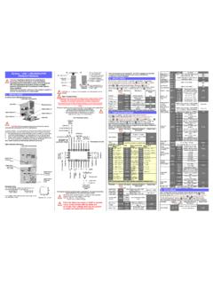
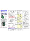
1 Dynisco Vertex Product Family Melt Hg Free Pressure Sensors Hg free Intrinsically safe pressure sensors designed specifically for extrusion and polymer processing applications Operating Manual P/N 974155 Rev 071715 ECO 45100 2 DYNISCO VERTEX QUICK START CARD This Quick Start setup guide can be used by experienced instrumentation technicians to configure the sensor using the Zero and Span actuators or via the optional HART communications. For more detailed information, please consult the complete Manual before Operating . The Quick Start procedure is intended for users already familiar with the use of Melt Pressure Sensors and Instrumentation. 1. Insure the process connection is clean and clear of any debris and is machined to the proper dimensions.
2 Machine tool kits with port gages are available (see sections 6 & 12 of Manual ) 2. Apply anti-seize as appropriate then install the sensor into the process connection. (Do NOT torque sensor into the hole at this time!) 3. Allow time for the sensor temperature to equalize to the process temperature. This will help eliminate thread galling and ease removal later. There should be NO pressure applied at this time. 4. Connect power to the sensor using the chart below. Standard configurations shown. See complete Manual for more options: mV/V Voltage mA 6-Pin 8-Pin Conduit 6-Pin 6-Pin 8-Pin Conduit Excitation Voltage 10-12 VDC 16-36 VDC Excitation Voltage 16-36 VDC SIG (+) A B RED A PWR/SIG (+) A A RED SIG (-) B D BLK B PWR/SIG (-) B B BLK PWR (+) C A WHT C RCAL (+) F E ORG PWR (-) D C GRN D RCAL (-) E D BLU RCAL (+) F F ORG F RCAL (-) E E BLU E 5.
3 After temperatures have equalized, apply torque (250 in-lbs typical) and tighten transmitter into mounting hole. 6. Perform Zero Function mV/V units can only be zeroed when feature is available on your indicator/controller. No local zero capability. Voltage units can be zeroed using on board zero potentiometer. Remove seal screw and adjust potentiometer until desired output is achieved. Replace seal screw when complete. mA units have a variety of on board Zero Adjustments types (based on configuration), potentiometer, pushbuttons, and HALL Effect Switches. 3 o For units with potentiometers, remove seal screw and adjust potentiometer until desired output is achieved. Replace seal screw when complete. o For units with pushbuttons, remove seal screw, using a 2mm or smaller Allen Key, depress pushbutton for sec, release pushbutton for sec, depress pushbutton for sec and release.
4 Replace seal screw when complete. o For units with HALL Effect Switches, unthread zero screw from endplate, depress screw, release screw, depress screw, release screw and return screw in endplate (failure to return the screw on units with HALL Effects Switches will cause the unit to go into failsafe). DYNISCO VERTEX QUICK START setup guide UTILIZING HART COMMUNICATOR This section only applies to mA HART units. 1. Follow steps 1 through 5 from DYNISCO VERTEX QUICK START setup guide . 2. Connect HART Handheld to the loop. 3. Power on the HART Handheld. See HART Command tree on the following page for reference. 4. From the Main Menu: a. Enter Tag (Quick Key 1, 3, 1). b. Set pressure units (Quick Key 1, 3, 2), if required. c. Set URV (Quick Key 1, 3, 3, 2) if output turndown (rescaling), is required.
5 D. Perform Zero Trim (Quick Key 1, 2, 5, 1, 3, 1) 5. Verify loop output is zero (4mA). 6. Remove HART Handheld from the loop. 4 MENU TREE 1 Device setup 1 Process Variables 1 PV Pres 2 Pv % rnge 3 PV AO 4 TV Snout temp 5 TV % rnge 6 TV AO 7 SV Elect temp 1 Alrms & Wrnings 2 Max. Pressure 3 Max. Electronics Temperature 4 Max. Snout Temp EEPROM Failure Gage Failure Watchdog Error Pushbutton Stuck Low Voltage Outside URV LRV Current SIM ON 2 Diag/Service 1 Device Status 1 Pressure 1 Rerange 1 Enter values 2 Apply values 2 Self Test 2 Temperature 3 Master reset 3 Recall Fact. Trim 2 Trim analog output 3 Sensor trim 1 PV LRV 2 PV URV 3 PV USL 4 PV LSL 2 PV Pres 1 Zero trim 2 Lower Sensor Trim 3 Upper Sensor Trim 4 Loop test 5 Calibration 6 Restore Factory Defaults psi bar kg/Sqcm % MPa KPa 4 Rcal 1 Rcal Set 1 Temperature Override 2 Trim analog Output 1 Temp Override Disable Enable 2 Temp Override Value 3 Basic setup 1 Tag 2 PV Unit 3 Range values 3 TV Snout Temp 4 Device Information 5 PV Damp 1 PV LRV 2 PV URV 3 TV LRV 4 TV URV 5 PV LSL 6 PV USL 7 TV LSL 8 TV USL 1 PV Pres 2 PV % rgne 3 PV AP 4 TV Snout temp 5 TV % rnge 6 TV AO 7 SV Elect temp 1 PV LRV 2 PV URV 3 PV USL 4 PV LSL 4 Detailed setup 1 Signal condition 1 Date 2 Descriptor 3 Message 1 Enter values 2 Apply values 2 Output condition 1 Process variables
6 3 Field Device Inf. 2 Rerange 5 Review psi bar kg/Sqcm % MPa KPa 4 PV LRV 1 PV LRV 2 PV URV 1 Model 2 Manufacturer 3 Dev id 4 Distributor 5 Poll addr 6 Num req preams 7 PV Unit 8 PV USL 9 PV LSL PV Min span PV Damp PV % rnge PV Xfer fnctn PV Rnge unit PV URV PV LRV Lower Trim Point Upper Trim Point TV C TV USL TV LSL TV % rnge TV Rnge unit TV URV TV LRV Write protect Tag Descriptor Message Date Universal rev Fld dev rev Software rev Hardware rev 3 PV Unit 4 PV Rnge unit 5 PV Min span 6 PV Damp 5 PV URV 1 PV LRV 2 PV URV psi bar kg/Sqcm % MPa KPa 7 SV C 1 Process variables 2 Analog output 3 HART output 1 PV Pres 2 PV % rgne 3 PV AP 4 TV Snout temp 5 TV % rnge 6 TV AO 7 SV Elect temp 1 Enter values 1 PV AO 2 TV AO 3 PV AO Alrm typ 4 Loop test 5 Calibration
7 Hi Lo Hold last out value 2 Apply values 1 PV LRV 2 PV URV 3 PV USL 4 PV LSL 1 Pressure 1 Rerange 2 Temperature 2 Trim AO 1 Poll addr 2 Num req preams 3 Burst mode 4 Burst option 3 Recall Fact. Trim 3 Sensor trim 1 Zero trim 2 Lower Sensor Trim 3 Upper Sensor Trim 1 Tag 2 Date 3 Descriptor 4 Message 5 Model 6 Local Pushbuttons 7 Revision #'s 8 Final asmbly num 9 Dev id Disable Enable Std Zero trim Off On Not used None Unknown Spcl 4 Rcal 1 Rcal Set 1 Temp Override 2 Trim AO 1 Temp Override Disable Enable 2 Temp Override Val 1 Universal rev 2 Fld dev rev 3 Software rev PV % range/current Process vars/crnt 5 TABLE OF CONTENTS 1 VERTEX CARE AND HANDLING .. 6 2 GENERAL .. 7 3 NOTES ON SAFETY .. 11 4 TECHNICAL DATA .. 18 5 TRANSPORT/DELIVERY/STORAGE.
8 23 6 INSTALLATION AND REMOVAL .. 24 7 COMMISSIONING .. 32 8 UTILIZING THE HART COMMUNICATIONS .. 35 9 MAINTENANCE .. 47 10 TROUBLESHOOTING .. 49 11 DYNISCO CONTACT INFORMATION .. 50 12 ACCESSORIES .. 51 13 APPROVALS/CERTIFICATES .. 55 14 OUTLINE DRAWINGS .. 58 6 1 VERTEX CARE AND HANDLING Be sure that the port where the Vertex transducer will be installed is free of all residual dried polymer from previous manufacturing processes (This is accomplished using Dynisco's machine whole tooling kit part number 200100). In applications where the Vertex transducer will be removed in between production runs, such as in the manufacture of food products or medical tubing, only remove the Vertex when the polymer is at, or near, full process temperature.
9 This will insure that you are pulling the transducer tip from molten conditions and therefore not causing any undue pulling effect on the diaphragm that could result in damage to the tip and a transducer that is then out of specification. If there is residual polymer material on the tip when the sensor is removed from a process port, NEVER use a wire brush, wire wheel, blunt or sharp instrument to remove the polymer. There are two acceptable ways of removing residual material from the tip of any pressure sensor: After removing the Vertex sensor, carefully clean the diaphragm with a soft cloth or bronze wool while the medium is still malleable. Do not attempt to clean the sensor by heating solidified polymer with a torch. A solvent bath consisting of glycol can be used to soften the polymer and improve removal.
10 Place the tip of the sensor into the solvent bath for a period of time as determined by when the residual polymer softens. Be careful to not immerse the electronics in the bath. This bath can be heated using heat elements to increase removal effectiveness and shorten cycle time. Then follow procedure a. above. When installing the Vertex sensor, it is important not to over-torque the unit into place. The unit should be hand tightened, and then tightened to the installation torque specified in section with a torque wrench. Adjust zero after installing and heating the machine to Operating temperature. Where filled sensors are sensitive to vertical orientation changes, Vertex is sensitive to horizontal orientation changes and installation torque.