Transcription of OPERATION AND MAINTENANCE MANUAL - Day …
1 Effective June 1, 2002 OPERATION AND MAINTENANCEMANUALDAY TANKSANDDAY TANK SYSTEMS ENGINE & COMPRESSOR ACCESSORIES4430 STEFFANI HOUSTON, TEXAS 77041 (713) 466-8679 FAX (713) 466-8686 TOLL FREE (800) 729-8807 receipt of the E&CA day tank, inspect the package for any signs of damage before signing the bill of lading. Ifthere is any visible damage, immediately notify the shipping company. Remove the top cover and inspect for possibledamage that might have occurred during shipment. All products are inspected at the point of shipment to ensure theyare free from any defects and are in good working condition. Dropping and other rough handling in transit could placestress or break welds and plumbing joints that will result in failure.
2 Electrical components or hardware may becomeloose during shipping. Check to ensure that the tank arrives in good TESTINGD uring fabrication, E&CA tanks are tested at 3 psi per UL-142 and checked a second time by quality control E&CA tanks are carefully tested for proper OPERATION . Power is applied to the unit and all aspects of the tankoperation are tested. Alarms are tested by manually changing control levels in the sequences of with contacts are tested for continuity during closed conditions. Float levels for pump motor controlsare tested for start up and shut down of the motor. Proper rotation of the pump and motor are checked while inoperation. All reset and test switches are checked for proper INSTALLATIONThe tank should be placed so that the various fuel and vent connections can be easily connected and inspected.
3 1"NPT pipe connections are located on the sides and rear of the day tank. Remove the shipping plugs from allconnection fittings. A minimum of 6" to 8" from any wall is required for installation. Mounting holes are provided inthe base of all E&CA day tanks. The tank should be bolted down before any piping is installed. This should eliminateany piping stresses due to misalignment. Always have the fuel system installed by trained, authorized personnel. E&CA tanks are designed for open venting(not pressurized fuel systems). Make sure the vents are properly installed and unobstructed. The tank must be ableto breathe to ensure normal OPERATION . All fuel piping should be of black iron pipe.
4 Brass, copper, or galvanized pipecan cause decomposition of fuel over extended periods of time. Pipe sizes should follow engine manufacturer srecommendations based on engine ratings plus distance and elevation between the main tank and engine. Theoverflow line should be equal to larger than the supply line. This line takes any overfill of the day tank and returns itto the main tank. The vent line should be piped vertically from the day tank above the highest point in the fuel the engine supply line per the manufacturer s recommendations. Flex hose requirement, pipe size, suctionlimitations and final connection should be specified. The fuel inlet to the day tank is located at the fuel transfer will be a d" NPT to 1" NPT connection depending on the pump(s) specified.
5 Piping clearances are provided inthe removable top cover. The engine fuel return line should be connected per the manufacturer s on engine requirements, fuel may be returned to the day tank at the same level and pressure of the fuelsupply line, or to a point located above the normal day tank fuel level. E&CA provides both connections on all INSTALLATIONA lways have the electrical system installed by trained, authorized personnel. E&CA day tanks are provided withterminal points for all customer connections. These points are located on easily accessible terminal strips under theremovable top cover. Power requirements and customer connections depend upon the number and types of optionsincluded on the day tanks.
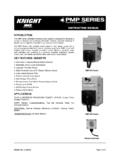
6 Please refer to the job specific E&CA wiring schematic (typical dual pump schematic shownabove) and the component wiring diagram included with the day AND MOTORSGENERAL INFORMATIONPUMPSThe standard pump is a 2 GPM Bronze Gear Pump. Otherpump models include: 4, 7, 10, and 20 GPM. The pump is directly driven from the shaft of the electricmotor by means of a flexible coupling. On the 2, 4 and 7 GPM pumps , an aluminum adapter connects the pump tothe DESCRIPTIONPump housings and gears are made of top quality bronze,shafts are 303 stainless steel. Bearings are designed ofhigh performance carbon-graphite material selected for wearresistance and long service life. Gear pumps are positivedisplacement pumps .
7 Each shaft revolution displaces adefinite amount of liquid relatively unaffected by the backpressure in the discharge line. Shaft speed and flow aredirectly proportional. Recommended pressure limits are 100 PSI for water and non-lubricants, 150 PSI for oil and otherlubricants. The maximum shaft speed is 1750 SEALSC lose coupled gear pumps are supplied with a Buna N AND TEMPERATURET hese pumps are suitable for all liquids that are compatiblewith bronze. Liquids containing solids, abrasives, powders,or paint pigments are definitely not recommended for gearpumps. A fuel strainer (E&CA option #215, 216 or 217)should be installed just ahead of the pump (and solenoidvalves, check valves, and other like devices) to keep debrisfrom entering the system.
8 The recommended liquidtemperature range is from 32 F to 140 F for best pump more extreme temperature conditions exist, factory shouldbe consulted. Freezing of pumps can cause damage andmust be avoided. Oils at low temperatures are very viscousrequiring a lower speed or extra LIFTAs a general rule, the suction lift should be kept at anabsolute minimum by placing the pump as close to the liquidsource as possible. A gear pump in new condition can lift20 feet of water in the suction line. A check valve (E&CAoption #255) is recommended at the beginning of thesuction line. For a first start-up, the pump should be primedusing a priming tee (E&CA option #282) to wet the pumpgears to avoid dry running.
9 Minimum size of the suctionpipe is the size of the pump inlet port. For longer suctionlines (over 3 feet) or for viscous liquids, the pipe should beat least one size or two sizes larger than the pump inlet AND RELIEF VALVEIf the discharge line contains any throttling devices such asa shut-off valve, a spray nozzle or other restrictive device, itis necessary to have a relief valve in the system whichreturns the liquid to the suction side or to the tank. The reliefvalve is also available as part of the pump itself (R-modelpumps). However, built-in relief valves are only good forintermittent service. If used continuously, the pump will over-heat. A built-in relief valve is strictly a safety device againstover pressure.
10 It will not work successfully as a pressure orflow control device. For this purpose a separate relief valvein the pressure line must be used. Unless otherwisespecified, the pump motor unit is supplied by the factory forshaft rotation counterclockwise from shaft end. Reversingmotor will reverse in and out ports and also requireschanging relief valve location. The relief valve is always onthe inlet side of this pump series. The factory pressuresetting is 50 PSIG. To increase pressure, turn the reliefvalve adjusting screw in a clockwise standard motor coupled to the 2 GPM pump has thesecharacteristics: 1/3 HP, 115 VAC, 1 PH, 60 Hz, ThermalProtected, FL Amps, Service Factor.