Transcription of 取扱説明書 Operation Manual - fpsc.twinbird.jp
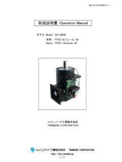
1 Ref. TWINBIRD CORPORATION (1/18) Operation Manual Model: SC-TD08 Name: 08 Stirling Cooler 08 TWINBIRD CORPORATION Ref. TWINBIRD CORPORATION (2/18) Restriction of Export 10 2019 11 The following regulations shall apply to Stirling Cooler and permission for export by the Ministry of Economy, Trade and Industry is required before exporting Stirling coolers from Japan for abroad. Foreign Exchange and Foreign Trade Law-section 1 of article 48. Foreign Exchange and Foreign Trade Law-section 1 of article 67. Export Trade Control Ordinance-section 2 of article 8. If you wish to export our Products from Japan for abroad, please contact us prior to exporting.
2 The above regulations were applied at the time of November 2019. Laws and regulations may be revised according to the legal revisions. Ref. TWINBIRD CORPORATION (3/18) Warning and Caution (1) (Free Piston Stirling Cooler, FPSC) DC24V DC12V AC100 240V The Stirling cooler (Free Piston Stirling Cooler, FPSC) must be used with a 24 V DC power source. Internal damage can result from operating this Stirling cooler directly with any input voltage other than 24 V DC. (2) When connecting the Drive PCB, do not make a reverse connection or short-circuit with adjacent terminals. It could cause Drive PCB broken. (3) 0 35 C The Stirling cooler is designed for use in ambient temperatures between 0 - 35 deg. C. Internal damage could result from operating the Stirling cooler outside this temperature range.
3 (4) -100 -20 C The cold side of the Stirling cooler should be maintained between -100 and -20 deg. C. Operation outside of this temperature range could result in internal damage to the Stirling cooler. To avoid the possibility of damaging to internal parts by overheating the Stirling cooler, do not apply heating elements directly to the cold side. (5) Use caution when handling the Heat Reject Fin assembly to prevent damage or injury. Inspect the Heat Reject Fin assembly for deformity or breakage before use. (6) FPSC Reduce the output setting of the Stirling cooler if unusual noises are observed coming from inside the pressure vessel. Please contact Twinbird if the reduced output setting does not eliminate the unusual noises.
4 (7) Avoid subjecting the Stirling cooler to excessive shock. It could cause internal damage. (8) Direct exposure of the Stirling cooler and PCB to water could cause electrical failure. (9) Direct exposure of the Stirling cooler and PCB to fire or excessive heat could cause internal damage. SC-TD08 08 SC-TD08 Stirling Cooler 08 Cold Side Drive PCB Heat Reject Fin Power Cord Balancer Copper Pipe Ref. TWINBIRD CORPORATION (4/18) (10) Warning: Placing the Stirling cooler into fire or excessive heat could cause expansion of the contained gas and explosion. (11) Do not put excessive strain on the electrical cords. It could cause damage to the wire and cause the Stirling cooler stop operating.
5 (12) To avoid the danger of burns, avoid touching the heat reject fin and certain parts on PCB with your bare hands during or immediately after Operation . (13) To avoid the danger of frostbite, avoid touching the cold side and its immediate surroundings with your bare hands during or immediately after Operation . (14) Please provide thermal insulation around cold side to prevent frost and dew condensation. If conditions require that you need to operate the Stirling cooler without thermal insulation, the cold side may develop a coating frost or water. If this occurs, please clean the cold side with a soft cloth.
6 Having frost or condensation on the cold side surface can cause an apparent reduction of cooling capacity. Also, if water drips down on a power cord or balancer as it defrosts, it could cause a short circuit or corrosion. Unusual vibration or noise of the Stirling cooler, or the breakage of the balancer can be caused by the corrosion of the balancer. (15) Failure of the Stirling cooler could result from subjecting the cold side to a strong force. It is made of thin stainless steel sheet surrounding a precision structure. (16) 1/4 When you intend to scrap the Stirling cooler, discharge internal gas from the cooler pipe by using 1/4 inch purging valve and then treat based on each country regulation. Also please work in the release space when pulling the gas out.
7 Ref. TWINBIRD CORPORATION (5/18) Specification Exterior Stirling Cooler Drive PCB Main Specification No. Item Specification 1 Product Dimension (Approximately) W 130 x D 130 x H 264 mm 2 Weight (Approximately) kg 3 Refrigerant (He) Helium 4 Amount of Refrigerant g 5 Inside Pressure of Stirling Cooler MPa 6 Power Source Voltage DC 24 V 10 % for Drive PCB 7 Rating Current 6A 10A 10A Prepare power supply with output current more than 10A for peak current 10A. 8 Cooling Capacity [ Condition] Ambient Temp.: 25 C Warm Side Temp.: 45 C Input Voltage to Set Output Voltage: 5V 25W 25 W and over Cold Side Temp.: -80 C 9 Ambient Temperature Range to Use 0 35 C 10 Acceptable Temperature Range at Cold Side -100 -20 C 11 Accessories (Drive PCB) Copper Pipe Thermistor ( ) Power Cord (Back side) Cold Side Warm Side ( ) (The part which heat reject fin is attached) Heat Reject Fin Ref.
8 TWINBIRD CORPORATION (6/18) Main Size (a) Stirling Cooler [mm] Ref. TWINBIRD CORPORATION (7/18) (b) Drive PCB [mm] 10 55 90 10 145 120 4- Hole ( max) 43 max 4 max Ref. TWINBIRD CORPORATION (8/18) of Stirling cooler(FPSC) Preparation (1) DC24V 6A 10A 10A (2) ( ) (3) (1)Power source: DC24V, Rating current:6A Prepare power supply with output current more than 10A for peak current 10A. (2)Temp. controller and Temp. sensor (3)Wire and Switch Wiring of the Drive PCB Drive of FPSC Please check connections before applying voltage. (1)DC24V (2) ON(CLOSE) (1)Turn on the Switch of Power supply. (2)Turn on the Switch of the Drive PCB.
9 Stop of FPSC (1) OFF(OPEN) (2)DC24V (1)Turn off the Switch of the Drive PCB. (2)Turn off the Switch of Power supply. Ref. TWINBIRD CORPORATION (9/18) Pin [SW1] DIP SW 0110 [CN7] : mm2 26 20 AWG : mm [SW2] DIP SW 0010(54 C) ( ) [SW3] DIP SW 1010(8A) ( ) 1 1 DIP SW DC V (CN8) AC 16 V 2(+) 2 DC 4 20 mA 3(-) (CN8) AC 16 V / High Low 5 High Low 6 1 High Low 7 2 High Low 8(0V) : DC V ( 10%) : 50 mA 9(+5V) [CN2] JST B2B-PH-K-E ( ) : JST PHR-2 1 2 [CN6] JST B2B-PH-K-S ( ) : JST PHR-2 1(+) : +0 V : 500 mA 2(-) [CN8] IDEC BP100-2PN10 : : N m ( kgf cm) 1 FPSC : AC 16 V (RMS) :9 A (RMS)( ) 2 [FG] mm ( ) - GND [CN1] IDEC BP100-2PN10 : : N m ( kgf cm) 1(+).
10 DC 24 V ( 10%) : 6 A 24V ( ) 2(-) 1 2 3 4 ON ON (1) OFF (0) 0 1 1 0 Ref. TWINBIRD CORPORATION (10/18) Input and Output of Drive PCB Pin Specification [SW1] DIP SW Setting of Output Voltage Change [CN7] PHOENIX CONTACT Acceptable Wire: - mm2, 26 - 20 AWG (Stranded conductor, Solid conductor) Strip Length: mm [SW2] DIP SW 0010(54 C) Setting of Warm Side Temperature Limit(Please use with this setting.) [SW3] DIP SW 1010(8A) Setting of Output Current Limit (Please use with this setting.) 1 Setting of Output 1 Input V DC Example of DIP SW and the Value Output (CN8) 16 V AC 2(+) Setting of output 2 Input 4 20 mA DC 3(-) Output (CN8) 16 V AC 4 Drive / Stop of FPSC Input High Low Function Stop Drive 5 Emergency Signal Output Output High Low Status Emergency Normal 6 Alarm Signal 1 Output Output High Low Status Alarm Normal 7 Alarm Signal 2 Output Output High Low Status Alarm Normal 8(0V) Reference Voltage Output Output Voltage: V DC ( 10%) Output Current Capacity: 50 mA 9(+5V) [CN2] JST B2B-PH-K-E (Blue) Acceptable Connector: JST PHR-2 1 Warm Side Thermistor 2 [CN6] JST B2B-PH-K-S (White) Acceptable Connector: JST PHR-2 1(+) Output to Fan Output Voltage: Power Source Voltage +0 V Output Current Capacity: 500 mA 2(-) [CN8] IDEC BP100-2PN10 - Screw: - Proper Torque: N m ( kgf cm) 1 Output to FPSC Output Voltage Range: 16 V AC (RMS) Output Current Capacity.
