Transcription of Operator’s Manual Lycoming
1 Operator s ManualLycomingO-360 SeriesApproved by FAA2nd EditionPart No. 60297-25652 Oliver StreetWilliamsport, PA. 17701 2007O-360 Series Operator s ManualLycoming Part Number: 60297-25 2007 by Lycoming . All rights and Powered by Lycoming are trademarks or registered trademarks brand and product names referenced in this publication are trademarks or registeredtrademarks of their respective additional information:Mailing address: Lycoming Engines652 Oliver StreetWilliamsport, PA 17701 :Factory:570-323-6181 Sales Department:570-327-7268 Fax:570-327-7101 Lycoming s regular business hours are Monday through Friday from 8:00 AMthrough 5.
2 00 PM Eastern Time (-5 GMT)Visitus on theWorld Wide Webat: S MANUALREVISIONREVISION DATE60297-25-1O-360 SERIES60297-25 June 2007 The page(s) in this revision replace, add to, or delete current pages in the operator s REVISIONCURRENT REVISIONNoneAugust 20083-5, 3-7 Lycoming SERIES OPERATOR S MANUALATTENTIONOWNERS, OPERATORS AND MAINTENANCE PERSONNELThis operator s Manual contains a description of the engine, its specifications, and detailed information onhow to operate and maintain it. Such maintenance procedures that may be required in conjunction withperiodic inspections are also included.
3 This Manual is intended for use by owners, pilots and maintenancepersonnel responsible for care of Lycoming powered aircraft. Modifications and repair procedures arecontained in Lycoming overhaul manuals; maintenance personnel should refer to these for such WARNINGN eglecting to follow the operating instructions and to carry out periodic maintenance procedures can resultin poor engine performance and power loss. Also, if power and speed limitations specified in this manualare exceeded, for any reason; damage to the engine and personal injury can happen.
4 Consult your localFAA approved maintenance BULLETINS, INSTRUCTIONS AND LETTERSA lthough the information contained in this Manual is up-to-date at time of publication, users are urged tokeep abreast of later information through Lycoming Service Bulletins, Instructions and Service Letterswhich are available from Lycoming distributors or from the factory by subscription. Consult the latestrevision of Service Letter No. L114 for subscription NOTEThe illustrations, pictures and drawings shown in this publication are typical of the subject matter theyportray; in no instance are they to be interpreted as examples of any specific engine, equipment or SERIES OPERATOR S MANUALIMPORTANT SAFETY NOTICEP roper service and repair is essential to increase the safe, reliable operation of all aircraft engines.
5 Theservice procedures recommended by Lycoming are effective methods for performing service of these service operations require the use of tools specially designed for the task. These special toolsmust be used when and as is important to note that most Lycoming publications contain various Warnings and Cautions whichmust be carefully read in order to minimize the risk of personal injury or the use of improper servicemethods that may damage the engine or render it is also important to understand that these Warnings and Cautions are not all inclusive.
6 Lycoming couldnot possibly know, evaluate or advise the service trade of all conceivable ways in which service might bedone or of the possible hazardous consequences that may be involved. Accordingly, anyone who uses aservice procedure must first satisfy themselves thoroughly that neither their safety nor aircraft safety will bejeopardized by the service procedure they SERIES OPERATOR S MANUALTABLE OF CONTENTSPAGESECTION 1 DESCRIPTION1-1 SECTION 2 SPECIFICATIONS2-1 SECTION 3 OPERATING INSTRUCTIONS3-1 SECTION 4 PERIODIC INSPECTIONS4-1 SECTION 5 MAINTENANCE PROCEDURES5-1 SECTION 6 TROUBLE-SHOOTING6-1 SECTION 7 INSTALLATION AND STORAGE7-1 SECTION 8 TABLES8-1vLYCOMING SERIES OPERATOR S MANUALLeft Side
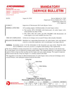
7 View O-360 (76 Series) Right Rear View O-360 (76 Series)viLYCOMING SERIES OPERATOR S MANUALSECTION 1-1 Cylinders .. 1-1 Valve Operating Mechanism .. 1-1 Crankcase .. 1-1 Crankshaft .. 1-1 Connecting Rods .. 1-2 Pistons .. 1-2 Oil Sump .. 1-2 Cooling System .. 1-2 Induction 1-2 Lubrication System .. 1-2 Priming System .. 1-2 This Page Intentionally Left SERIES OPERATOR S MANUALSECTION 1O-360 DESCRIPTIONSECTION 1 DESCRIPTIONG eneral The Lycoming O-360 76 Series aircraft engine is a four cylinder direct drive, horizontallyopposed, wet sump, carbureted, air cooled referring to the location of the various engine components, the parts are described in their relationshipto the engine as installed in the airframe .
8 Thus, the power take-off end is considered the front and accessorydrive end the rear. The sump section is considered the bottom and the opposite side of the engine where theshroud tubes are located the top. References to the left and right side are made with the observer facing therear of the engine. The cylinders are numbered from the front to the rear, the 1 and 3 cylinders are on theright side, 2 and 4 cylinders are on the left. The direction of rotation of the crankshaft is clockwise, viewedfrom the rear of the engine.
9 The direction of rotation for the accessory drives is determined with theobserver facing the drive letter L in the model prefix denotes the reverse rotation of the basic model. Example:O-360-E1AD has clockwise rotation of the crankshaft; therefore, LO-360-E1AD has acounterclockwise rotation. Likewise the rotations of the accessory drives of the LO-360-E1AD are opposite those of the basic letter D used as the 4thor 5thcharacter in the model suffix denotes that the engine isequipped with a dual magneto housed in a single aspects of engines are the same and performance data and specifications for thebasic models will The cylinders are of conventional air cooled construction with two major parts, head and barrel,screwed and shrunk together.
10 The heads are made from an aluminum alloy casting with a fully machinedcombustion chamber. The rocker box is cast as an integral part of the cylinder head which forms the housingfrom both intake and exhaust valve rockers. The cylinder barrels, which are machined from chrome nickelmolybdenum steel forgings, have deep integral cooling fins and the inside of the barrels are ground andhoned to a specified Operating Mechanism A conventional type camshaft is located above and parallel to the camshaft actuates the hydraulic tappets which operate the valves through push rods and valve rockers are held in place by the use of rocker arm fulcrum.