Transcription of OPNET ModelerIntroduction to Using SIMULATION AND …
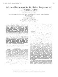
1 Introduction to Using OPNET ModelerSYSC 4005/5001 SIMULATION AND MODELINGR eference: OPNETWORK2002 Outline Introduction SIMULATION Overview Events and Event List Concepts Network Modeling Node Modeling Link Modeling Process Modeling Running Simulations Collecting and Analyzing Results ConclusionNote: You don t have to use OPNET Modeler for your project! SIMULATION MethodologyYesEndStartResults statistically useful?NoNoResults sufficiently detailed?Choosing input andrunning simulationsSystem results accurate?Defining input and outputSpecifying the system modelNoChoosing aspectsto be modeledUnderstanding your goals for the simulationUnderstanding the systemThe Project/Scenario Workflow Create project Create baseline scenario Import or create topology Import or create traffic Choose results and reports to be collected Run SIMULATION View results Duplicate scenario Make changes Re-run SIMULATION Compare resultsIterateThe Three-Tiered OPNET Hierarchy Three domains: network, node, and process Node model specifies object in network domain Process model specifies object in node domainProcess model rip_udp_v3 Network Domain.
2 Network ObjectsGeneric Devices Network models consist of nodes, links andsubnets Nodes represent network devices and groups of devices Servers, workstations, routers, etc. LAN nodes, IP clouds, etc. Links represent point-to-point and bus links Icons assist the user in quickly locating the correct nodes and links Vendor models are distinguished by a specific color and logo for each companyVendor DevicesNode Domain Basic building blocks (modules) include processors, queues, and transceivers Processors are fully programmable via their process model Queues also buffer and manage data packets Transceivers are node interfaces Interfaces between modules Packet streams Statistic wiresReceiverTransmittersProcessorQueues Stat WirePacket Stream OPNET process models consist of State transition diagrams Blocks of C code OPNET Kernel Procedures (KPs)
3 State variables Temporary variables A process is an instance of a process model Processes can dynamically create child processes Processes can respond to interruptsProcess DomainSimulation Output Three kinds of output Vectors List of time-value pairs Scalars List of values dependent on parametric input Not plotted vs. time Animations Packet flows Node movements Objects have pre-defined statistics For example: throughput, bits received, bits forwarded, and Event List ConceptsEvent-Driven SIMULATION Events are specific activities that occur at a certain time OPNET simulations are event-driven SIMULATION time advances when an event occurs A different method might be to sample at regular intervals Disadvantages.
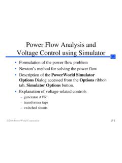
4 Accuracy of results is limited by the sampling resolution SIMULATION is inefficient if nothing happens for long periodsTimeEvent Type List Concepts Single global event list Shared SIMULATION time clock Events scheduled in time order Event removed from event list when it completesEvent List Example Consider this model:Network modelNode modelNode modelNode model: srcNode model: dest1 Network modelEvent List Example (cont.) The network model has three nodes (src, dest1,dest2) relying on two node models (both dest nodes use the same node model) In the srcnode model, packets are generated at genand sent by queueto either transmitter (tx0 / tx1) Packets then flow across a link to a destination node (dest1, dest2) where they are received (rx) and thrown out (sink) Three modules (gen, queue,andsink) have process models associated with themForced States Forced (green) and unforced (red) states differ significantly in execution timing In a forced state, the process.
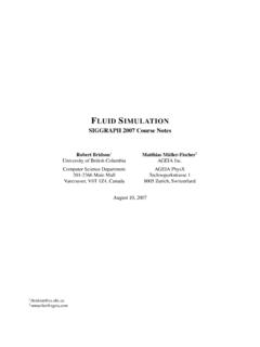
5 Invokes the enter executives Invokes the exit executives Evaluates all condition statements If exactly one condition statement evaluates to true, the transition is traversed to the next state OPNET convention: code in enter execs onlyTransition to next stateTransition to next stateForced (green) statesEnter execs invokedNo blocking or waitingExit execs invokedEnter execs invokedExit execs invokedNo blocking or waitingUnforced States In an unforced state, the process: Invokes the enter executives Places a marker at the middle of the state Releases control to the SIMULATION Kernel and becomes idle Resumes at the marker and processes the exit execs when next invokedStart of invocationEnd of invocationUnforced (red) statesTransition to next stateBlocking, waitingfor invocationExit execs processed when invocation occursEnter execs invokedNext invocationstarts hereBlocking, wait for next invocationProcess Model Example Model with three forced states and one unforced state:3.
6 Transition Transition Exit execs invoked immediately. Transition condition(pk_count == 0)evaluates to Exit execs invoked Marker is placed and process stops Enter execs Enter execs Initial interrupt delivered and the enter execs the SIMULATION SIMULATION Kernel reads the event at the head of the event list, and delivers control to the process in the Process begins execution at the initial state, marked with the black arrow Process executes the Init state s enter execsTimeEvent Termination Simulations terminate in one of four ways: The event list is emptied SIMULATION attribute durationexpires A process calls for termination, Using the KP op_sim_end() A fatal error occursHow Does Time Advance?
7 SIMULATION time advances only when an event with a later time is processed from the event list No SIMULATION time occurs during the execution of a process No time elapses during transitions between states A process model must always have an unforced (red) state so time can advance Avoid endless looping betweenforced (green) statesPacketsPackets Information-carrying entities that circulate among system components General data structures, organized into fields of user-defined information Dynamically created and destroyed as the SIMULATION progresses A single system may rely on multiple types of packets with different formatsPacket Formats Packets can either be unformatted or formatted Unformatted packets have no user-defined data fields Formatted packets have zero or more fields of type Integer Floating point Structure Packet InformationEvents for Packet Transmission All packet transmissions are modeled with 4 events Start of Transmission End of Transmission Start of Reception End of Reception SIMULATION Kernel automatically schedules the eventsNetwork ModelingCreating Network Models There are
8 Two ways to create new network models Manual Creation Drag and drop Rapid configuration Import from network management tool HP Network Node Manager Tivoli Netview Router configuration files ATM text files XML ACE VNE ServerRapid configuration Rapid configuration allows you to quickly create networks of any size Available topology configurations:Bus; Ring; Star; Tree; Unconnected Net; Mesh (Full or Randomized) You control the number of nodes, the node and link models used, how nodes will be arranged, and node locations within the workspaceStartup Wizard The Startup Wizardcan quickly configure a new scenario There are several settings for each scenario: Name Initial topology Network scale Network size TechnologiesObject Attributes All objects have attributes that control aspects of their behavior Attributes may vary from one model to the next Attribute values may vary between objects of the same model type Right-click on an object and select Edit Attributes to view or change its attributesNode ModelingNode Objects.
9 Processors and Queues Processors General-purpose building blocks of node models Fully programmable Queues Offer all the functionality of processors Can also buffer and manage a collection of data packetsProcessorQueueLink ModelingLink Types Link objects model physical layer effects between nodes, such as delays, noise, radio link, established during a SIMULATION , can be created between any radio transmitter-receiver channel pair. Satellite and mobile nodes must use radio links. Fixed nodes may use radio links. A radio link is not drawn but is established if nodes contain radio bus link transfers data among many nodes and is a shared point-to-point link transfers data between two fixed linkLink Editor Create or modify links Choose link types Modify attributesVerify Links Verify links before running a SIMULATION Ensures that point-to-point and bus link connections are valid Enough transmitters and receivers to support all of the incoming and outgoing links Data rates of the connected transmitter and receiver match the data rate of the link Transceivers support the attached link technologyProcess ModelingProcess Models Process models represent algorithms Communications
10 Protocols and algorithms Shared-resource managers Queuing disciplines Specialized traffic generators Statistic-collection mechanisms Control Processes Process Editor provides the features for creating process modelsState Transitions Transitions connect states Conditional Unconditional Transition executive Exactly one condition must evaluate to true If the condition statement (x == y)is true, the transition executive (Reset_Timers)is invokedTransition executiveCondition statementState Executive Blocks Each state has two executive blocks Enter executives are invoked upon entering a state Exit executives are invoked before exiting a state State transition diagrams C programming language Library of OPNET Kernel Procedures (KPs) State variables (private to each process)