Transcription of Optical waveguide analysis using Beam Propagation Method
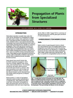
1 1 OOppttiiccaall wwaavveegguuiiddee aannaallyyssiiss uussiinngg BBeeaamm PPrrooppaaggaattiioonn MMeetthhoodd Term Paper for Introduction to Optoelectronics spring 2006 Prof. Frank Barnes Page 10: My MATLAB implementation of double slit diffraction using beam Propagation Method Sri Rama Prasanna Pavani Micro- Optical Imaging Systems Laboratory University of Colorado at Boulder 2 Introduction Closed form analytical solutions for the wave equation can be easily determined only for a few symmetrical structures such as cylindrical and slab waveguides. In complicated structures with bends such as y-couplers, analytic closed form solutions cannot be derived.
2 Figure 1a: Cylindrical waveguide Figure 1b: Y Coupler The Y-Coupler, as shown in Figure 1b, couples an input waveguide to two output waveguides. As the mode would dynamically change as the wave propagates through such structure, it is hard to determine the losses using analytical methods . beam Propagation Method can be efficiently used for analyzing such structures. 3 beam Propagation Method The beam Propagation Method is a numerical way of determining the fields inside a waveguide . With this Method , the mode profile of an unusual waveguides such as y-couplers can be determined with ease.
3 The dynamic mode profile can be accurately estimated as the wave propagates through the wave guide. The beam Propagation Method essentially decomposes a mode into a superposition of plane waves, each traveling in a different direction. These individual plane waves are propagated through a finite predetermined distance through the wave guide until the point where the field needs to be determined has arrived. At this point, all the individual plane waves are numerically added in order to get back the spatial mode. Figure 2: My simulation of the diffraction of a Gaussian beam using BPM This process precisely corresponds to the Fourier way of analyzing.
4 Specifically, according to Fourier theory, any periodic signal can be decomposed into complex sinusoids of different frequencies. When all of these sinusoids are added, we would get back the original signal. In beam Propagation Method , a mode is decomposed into different plane waves, which indeed are sinusoids of different frequencies. The basic idea here is to split a complicated problem into a simpler problem for which solutions are obvious. Since wave equation is linear, all these simple solutions can be added back to obtain the complicated solution.
5 For instance, in Figure 2, I have numerically computed the diffraction of a Gaussian beam as it propagates through a medium. 4 Principle of superposition This principle is forms the foundation of the beam Propagation theory. The principle of superposition states that, for a linear system, a linear combination of solutions to the system is also a solution to the same linear system. The superposition principle applies to linear systems of algebraic equations, linear differential equations, or systems of linear differential equations.
6 Since we are considering a linear medium, the superposition principle is valid. Consider a slab waveguide as shown in Figure 3. Any guided field inside this wave guide should necessarily satisfy the wave equation. If the medium is isotropic, then plane waves are natural solutions of the wave equation. Figure 3: Slab wave guide Since the wave equation is linear, any linear superposition of solutions will also constitute a valid solution. This important fact forms the foundation of the beam Propagation theory. In order to describe the general mode of a waveguide , a superposition of plane waves, each with identical angular frequency, but different Propagation vector, would be used.
7 Thus, the essence of the theory is that plane waves form a basis set for the mode description. 5 Fundamental mode of a Hermite Gaussian beam In this section, let us see, how the Gaussian amplitude profile, which is the fundamental TEMoo mode can be represented in the form of a superposition of plane waves. Analytically, a Gaussian can be represented as Figure 4a Figure 4b Figure 4c Figure 4a: Gaussian beam profile of a HeNe laser, which I captured after spatial filtering.
8 Figure 4b: An ideal simulated Gaussian beam profile Figure 4c: 3D plot of a Gaussian The idea here is to split the above Gaussian into number of plane waves weighted by complex factors known as Fourier coefficients. The Fourier and inverse Fourier transforms are characterized as follows. In the first equation, f(x) (Gaussian), is represented just as an integral of weighted sinusoids. Note that F(k)s are mere complex numbers that act as weighting factors of the sinusoids. In the beam Propagation approach, it can be rightly said that the Fourier kernel, that is, the sinusoids (with different k s) are infact plane waves with different Propagation vectors.
9 Thus, in short, with the above expression, any finite analytical function can be represented as a sum of plane waves. Note that this is possible only since the Fourier transform is linear. 6 For a Gaussian beam , the Fourier coefficients can be shown to be 2202201)(xkxexkF = The whole theory explained above is represented by the following picture (Figure 5). Figure 5: The Gaussian beam represented in terms of multiple plane wave components. In order to obtain an appreciation for the above picture, we should first have an appreciation of the Propagation vector K.
10 The total magnitude of K is identical for all components in a mode. However, the relative sizes of Kx and Kz vary. Since Ky is assumed to be zero in the above picture, the wave propagates only in the xz plane, and therefore 22zxKKK+= Consequently, Kz is maximum when Kx is zero, which can be clearly seen from in Figure 5. Thus the axial Propagation vector is the vector with highest magnitude. As Kx increases, the amplitude of the plane wave decreases. The spatial amplitude distribution of the Gaussian is essentially comprised by the amplitude and the direction of the individual plane waves.