Search results with tag "Microstrip"

Modern Antenna Design - Radio Astronomy
www.radio-astronomy.org6 Microstrip Antennas 285 6-1 Microstrip Antenna Patterns, 287 6-2 Microstrip Patch Bandwidth and Surface-Wave Ef ciency, 293 6-3 Rectangular Microstrip Patch Antenna, 299 6-4 Quarter-Wave Patch Antenna, 310 6-5 Circular Microstrip Patch, 313 6-6 Circularly Polarized Patch Antennas, 316 6-7 Compact Patches, 319 6-8 Directly Fed Stacked Patches, 323

High Speed Layout Design Guidelines - NXP
www.nxp.comabove GND is much slower in a stripline layout comp ared with a microstrip la yout. A stripline layout has a signal sandwiched by FR-4 material, whereas a microstrip layout has one conductor open to air. This exposure causes a higher, effective dielectric constant stripline layout compared to microstrip layouts.

MICROWAVE GROUP - MRC GIGACOMP - Markets …
www.mrc-gigacomp.com4 RF Isolators & Circulators JQL Product Profile DROP-IN WAVEGUIDE SURFACE MOUNT MICROSTRIP SURFACE MOUNT COAXIAL ISO-ADAPTER MICROSTRIP

HELICAL SHAPED MULTIBAND MICROSTRIP ANTENNA FOR …
arresearchpublication.comHELICAL SHAPED MULTIBAND MICROSTRIP ANTENNA FOR WIRELESS COMMUNICATION Mr. Sanjay Sharma1, Mr. Vijay Kumar Singh2 ... a brief review of square spiral patch design is discussed. Keywords: Helical, IE3D, VSWR, Return loss ... strip antennas”, ch. 5 of Advances in Micro strip and Printed Antennas, K. F. Lee, Editor, John Wiley,

Design and Analysis of Stepped Impedance Microstrip Low ...
www.ijsrp.orgInternational Journal of Scientific and Research Publications, Volume 3, Issue 8, August 2013 1 ISSN 2250-3153 www.ijsrp.org Design and Analysis of Stepped Impedance Microstrip

Multiband Wireless Microstrip Antenna with Embedded …
www.enggjournals.comMultiband Wireless Microstrip Antenna with Embedded Meta-materials for MIMO Arun Balan1, R.Ramesh2, Usha Kiran K.3 School of Electronics Engineering, VIT University, Chennai, Tamil Nadu, India 1arun.balan2013@vit.ac.in 3usha.kiran@vit.ac.in 2ramesh.r@vit.ac.in
Design of a Dual Patch Triangular Microstrip Antenna - N5DUX
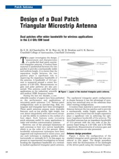
n5dux.comPatch Antenna Design of a Dual Patch Triangular Microstrip Antenna Dual patches offer wider bandwidth for wireless applications in the 2.4 GHz ISM band

DESIGN OF MICROSTRIP ANTENNA FOR WIRELESS …
www.jatit.orgFigure 3: Microstrip Patch Antenna [12] It is seen from Figure that the normal 5 components of the electric field at the two edges out of phase since the patch …

A Circularly Polarized 60 GHz Microstrip Antenna - …
www.n5dux.comA Circularly Polarized 60 GHz Microstrip Antenna Here is a mm-wave antenna suitable for WLAN systems By V. A. Volkov, M. D. …
Introduction to Microstrip Antennas
courses.egr.uh.eduThe basic principles are illustrated here for a rectangular patch, but the principles apply similarly for other patch shapes. We use the cavity model to explain the operation of the patch antenna. 29 Y. T. Lo, D. Solomon, and W. F. Richards, “Theory and Experiment on Microstrip Antennas,” IEEE Trans. Antennas Propagat

MT-094: Microstrip and Stripline Design - Analog Devices
www.analog.comMicrostrip and Stripline Design . INTRODUCTION . Much has been written about terminating PCB traces in their characteristic impedance, to avoid signal reflections. However, it may not be clear when transmission line techniques are appropriate. A good guideline to determine when the transmission line approach is necessary for logic signals

Synthesis and Analysis of Microstrip and Stripline ...
colinrrobinson.comSYRACUSE UNIVERSITY Synthesis and Analysis of Microstrip and Stripline Transmission Line Structures Project 1 Colin Robinson Thomas Piwtorak Bashir Souid
MT-094: Microstrip and Stripline Design - Analog …
www.analog.comRev.0, 01/09, WK Page 1 of 7 MT-094 TUTORIAL Microstrip and Stripline Design . INTRODUCTION . Much has been written about terminating PCB traces in their characteristic impedance, to avoid

AN-1469PHYTER Design & Layout Guide
www.ti.comMDI (TP/CAT-V)Connections www.ti.com 2.2 Calculating Impedance The following equations can be used to calculate the differential impedance of the board. For microstrip traces, a solid ground plane is needed under the signal traces.

DESIGN OF LINEARLY POLARIZED RECTANGULAR …
ethesis.nitrkl.ac.indesign of linearly polarized rectangular microstrip patch antenna using ie3d/pso a thesis submitted in partial fulfillment of the requirements for the degree of

マイクロストリップアンテナ回想録
ap.ei.tuat.ac.jp年内容 1951 [1] R. M. Barrett et al, “Microwave printed circuits,” 1952 [2] D. D. Grieg et al, “Microstrip – A New Transmission Technique for the

Realization of Microstrip Band-Pass Filter Design
ijarcet.orgInternational Journal of Advanced Research in Computer Engineering & Technology (IJARCET) Volume 3 Issue 12, December 2014 ISSN: 2278 – 1323 4242 All Rights ...

Simulating Dielectric and Conductor Loss - iMAPS Ne
imapsne.orgmicrostrip model FR4 dielectric substrate –εr=4.3, tg δ=0.025 Comparison of Results for Simple Model . CST – COMPUTER SIMULATION TECHNOLOGY | www.cst.com FR4 dielectric substrate –εr=3.5, tg δ=0.06 50mm long stripline model Measured and Simulated Data for Stripline . CST – COMPUTER SIMULATION TECHNOLOGY | www.cst.com Equation, such ...

Digital Signals Integrity Tutorial - Sonnet Software
www.sonnetsoftware.comDigital Signals Integrity Tutorial Sonnet Microstrip Models Thanks to Sonnet’s Application Engineer, Greg Kinnetz and the TCNJ Spring 2014 ELC 441 Digital Engineering Systems Class, Adrian Alshuaili, Ricardo Alves, George Banis, Jason Boxer, Vincent Carbone,

PCI Express* Board Design Guidelines
www.linelayout.comFigure 1-12. Trace Width and Spacing Recommendations for Microstrip ..... 21 Figure 1-13. Trace Width and Spacing Recommendations for Stripline..... 22 Figure …

40nm LP-RF Foundry Technology - GLOBALFOUNDRIES
www.globalfoundries.comMicrostrip line, co-planar waveguide, slow -wave co-planar waveguide, 45/90 degree bend, tee junction

RT/duroid 5870 /5880
rogerscorp.com• Microstrip and Stripline Circuits • Millimeter Wave Applications • Military Radar Systems • Missile Guidance Systems • Point to Point Digital Radio Antennas Advanced Connectivity Solutions 100 S. Roosevelt Avenue, Chandler, AZ 85226 Tel: 480-961-1382 Fax: 480-961-4533 www.rogerscorp.com

NATIONAL INSTITUTE OF TECHNOLOGY DELHI
nitdelhi.ac.inMiniaturized UWB BPFs, Antenna (Microstrip line based), Silicon Integrated Waveguide(SIW) Antennas, Reconfigurable Antenna, Filtantenna (Filter+Antenna), 2-D and 3-D Antenna Design, RF/Green Energy Harvesting, High Frequency Circuit Design Artificial Intelligence & Machine learning Graph machine learning and graph deep learning
High-Speed Layout Guidelines - Texas Instruments
www.ti.comStripline 1 0.5 4.6 0.466 139.8 715.3 Stripline 2 1 4.6 0.466 139.8 715.3 1.3.2 Characteristic Impedance, Reflections, and Termination Another property of a transmission line is the characteristic impedance, Z0. The microstrip in Figure 4 has for the given attributes a characteristic impedance Z0 = 105 Ω, and the stripline Z0 = 55 Ω. If there ...

JESD204B Physical Layer (PHY) - Texas Instruments
www.ti.commicrostrip or stripline lanes (S<=W) • 100 differential impedance • Avoid 90 turns – Reduces +/- trace mismatch – Reduces impedance discontinuity • Recommend 0201 series components (AC coupling) to minimize impedance discontinuity of pads • Routing on inner layers (stripline) has ...

Planar Electromagnetic (EM) Simulation in ADS - Chapter 4
www.keysight.comMar 18, 2021 · Case Study 2: Design and Simulation of a Patch Antenna Theory A microstrip antenna in its simplest configuration consists of a radiating patch on one side of a dielectric substrate, which has a ground plane on the other side. The patch conductors are usually made of copper or gold and can be any shape.

Microstrip Propagation Times Slower Than We Think
www.ultracad.comMicrostrip Propagation Times Slower Than We Think 2 Case (b) illustrates the same trace, but with a thinner spacing between the trace and plane.

Microstrip Patch Antenna Design - Santa Clara University
linux.students.engr.scu.edu– But illustrates sizes and importance of good antenna design • Why microstrip antennas? – The patch antenna is a good place to start for antenna fundamentals With more coming: 5G (or whatever), Wireless Display, Wireless USB, etc.

Microstrip and CPW Power Divider Design - Chapter 8
www.keysight.comMar 10, 2021 · medium such as a microstrip, stripline, coplanar waveguide, etc. A 3-port network cannot be lossless, reciprocal, and matched at all the ports. Therefore, since a T-junction power divider is lossless and reciprocal, it cannot be perfectly matched at all of the ports. The T-Junction power divider can be

Microstrip, Stripline,CPW,and SIW Design
www.qsl.netMaterial Properties • Relative Permittivity ε r (or Dielectric Constant Dk) and Dissipation Factor (Df). - Dk is the property of a material which alters the Electric field in the wave. - Dk = ɛ-jɛ’, where: ɛ = energy stored, and ɛ’ = energy lost. - Materials used in PCB technology generally have Dk from 2 to 10 (Dk is dimensionless). - Generally, dielectric constant Dk, decreases as ...
Microstrip, Stripline, and CPW Design - QSL.net
www.qsl.netSkin Depth of Planar Conductors At high frequencies, the current flowing in a conductor tends to get confined near the outer surface of the conductor.
Similar queries
Modern Antenna Design, Microstrip, Stripline, HELICAL SHAPED MULTIBAND MICROSTRIP ANTENNA, HELICAL SHAPED MULTIBAND MICROSTRIP ANTENNA FOR WIRELESS COMMUNICATION, A brief, Antennas, Design and Analysis of Stepped Impedance Microstrip, Multiband Wireless Microstrip Antenna with Embedded, Dual Patch Triangular Microstrip Antenna, Antenna, OF MICROSTRIP ANTENNA FOR WIRELESS, Patch, Circularly Polarized 60 GHz Microstrip Antenna, Patch antenna, Microstrip and Stripline Design, Analog Devices, Transmission, Microstrip and Stripline Transmission Line Structures, MT-094: Microstrip and Stripline Design - Analog, Design & Layout Guide, DESIGN OF LINEARLY POLARIZED RECTANGULAR, Design of linearly polarized rectangular microstrip patch antenna, Realization of Microstrip Band-Pass Filter Design, Digital Signals Integrity Tutorial, PCI Express* Board Design Guidelines, 40nm LP-RF Foundry Technology, Junction, Microstrip and Stripline, High-Speed Layout Guidelines, Texas Instruments, JESD204B Physical Layer PHY, Design, Microstrip antenna, Microstrip Propagation Times Slower Than, Microstrip Patch Antenna Design, Antenna design, Microstrip, Stripline,CPW,and SIW Design, Microstrip, Stripline, and CPW Design, Confined