Transcription of Optimize your vacuum distribution network for a …
1 PROCESS technology . Optimize your vacuum distribution network for a maximum point-of-use vacuum - part 1. vacuum piping Frank Moerman, European Hygienic Engineering & Design Group - Belgium Air leaks and pressure drop in the vacuum distribution Monitor for h) in the entire system. Because system result in poor vacuum at the points-of-use. airtightness leakage characteristics differ Valves can be provided at several between a pressure-test and a Properly designed and installed vacuum systems places in the vacuum line, to vacuum operation, particularly in are less susceptible to fluctuations in production determine if air leakage occurs in components, such as valves and vacuum load, which can result in higher productivity, the upstream piping of the vacuum flanges, pressure testing is only system.
2 However, too much isola- successful to find large leaks as it better-formed products and enhanced product quality tion valves increase pressure drop. does not discover the small leaks or safety. As an example, in the semiconductor The most commonly used test that inevitably develop as the industry, oxygen from an air in-leak can chemically methods to determine the presence system ages (Umrath et al., 2007;. of air leaks are the following: Hesser, 2008). react with silane to produce sand, SiO2, not the With the foam-spray test, the desired semiconducting solid. In the food industry, A pressure test with oil-free contractor can register the forma- improper vacuum during packaging may compromise nitrogen allows to measure the tion of bubbles in a soapy solu- the safety of the food product.
3 Decrease in pressure over a cer- tion applied to leaking joints of tain period of time (usually 24 a system under pressure (Umrath Design for airtightness vacuum lines must be completely airtight to guarantee their proper functioning to a maximum. vacuum leaks in the piping components of the vacuum system could lead to insufficient vacuum capacity, and they also can allow non-condensable gases into the system as well as condensable contaminants. Even small quantities of both can take up large volumes, requir- ing higher-capacity vacuum sources, as well as bigger system components. An increase in the non-condensable load may also cause an unstable vacuum , because non-condensable loads must always travel through the vacuum source.))
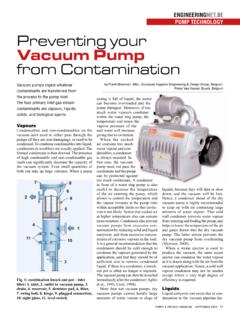
4 To minimize losses over the length of the suction line, the vacuum source should be installed in a technical corridor or mechanical room as close as possible to the process for efficient vacuum . Too long vacuum distribution lines increase the risk for air leaking within the vacuum system. The consequence is that the vacuum source must operate at an elevated level of vacuum to compensate for that leakage of air into the vacuum system. However, higher vacuum levels may open more leaks Fig. 1: ultrasonic leak detection. (Bott, 2006; Hesser, 2008). Pumps, Water & Process - september 2013 27.
5 PROCESS technology . Smallest detectable Quantitative the location of the leak site. The advantages Method Test gas Pressure range leak rate measurement of ultrasonic leak detection include versatil- ity, speed, ease of use, the ability to perform Air and other tests while equipment is running, the ability Pressure drop test 10-4 Positive pressure Yes to find a wide variety of leaks and its accu- gases racy (Senternovem, 2010). Foaming liquids Air and others 10-4 Positive pressure No In table 1 a comparison is made between different air leak detection methods, more specifically their air leak detection potential.
6 Pressure rise test Air 10-4 vacuum Yes Air and other Design for minimal pressure Bubble test 10-3 Positive pressure No drop gases Pressure drop is the difference between the 10-12 vacuum , vacuum level at the vacuum source inlet Helium leak helium Yes and the vacuum level at the end-use point. detection 10-7 Postive pressure In rough vacuum , pressure drop in piping Ultrasonic may not be larger than 50 mbar. In general, Air and others 10-2 Positive pressure No allowable pressure drop for piping systems microphone is of the order of magnitude of 10% of the Table 1: comparison of leak detection methods (Umrath et al.)
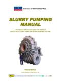
7 , 2007). absolute vacuum pressure. This means that, for example, a 10 mbar vacuum system can tolerate only 1 mbar of line pressure drop. As depth of vacuum increases, the allowable pipeline pressure drop is proportionally less. Fig. 2: use a If the system piping and equipment do not wye or swept have an adequately-low pressure drop, then T (with 30-60 no matter how big the vacuum -generating angle between device is, it can never achieve the desired both branches) level of vacuum (Fay et al., 2000; Sentern- instead of a tee. ovem, 2010). Too long vacuum distribution lines are prone to higher pressure drops due to fric- et al.
8 , 2007). Then the vacuum system is opened to the tion. But apart from too long pipe runs, inad- In the rate-of-rise test, the entire system leak detector, and the helium-content is equate (restrictive) vacuum piping diameter is lowered to a vacuum deeper than operat- measured at the inside of the vacuum system is also a major contributor to pressure drop. ing pressure, and the rise in pressure is (Senternovem, 2010). Proper pipe dimensions will help to limit monitored over a period of time. Given the In ultrasonic detection, an ultrasonic detec- vacuum fluctuations. As a rule of thumb, system volume, leakage can then be calcu- tor is used to register the sound of in-leaking on single vacuum pump applications, the lated accurately.
9 It is recommended to run air. An ultrasonic acoustic detector can diameter of the vacuum pump inlet should this test on individual components of the recognize the high-frequency hissing sounds be maintained as far into the process as system (piping, equipment, filters, knockout associated with air leaks. Portable ultrasonic possible. If the vacuum system has to be pots, etc.) as accurately as you can. The rate- acoustic detectors consist of directional installed further away from the process, it is of-rise over 24 hours for a given component microphones, amplifiers, audio filters, and even recommended to oversize the vacuum of the vacuum system should be 10% or less usually have either visual indicators or line upstream of the vacuum source to mini- of the operating vacuum absolute pressure earphones to detect leaks.
10 The principle mize the overall line pressure drop. With (Fay et al., 2000; Hesser, 2008; Umrath et behind ultrasonic leak detection is simple. increasing depth of vacuum , the vacuum line al., 2007). In a vacuum leak, the leak flows from a sizes increase. When several pump systems A vacuum test with a cream applied to all high-pressure laminar to a low-pressure operate in parallel on a common manifold, joints and potential leak points also is used turbulent flow. That turbulence generates a the line size of the manifold should be to find air leaks. The cream will be sucked noise which contains a broad spectrum of minimal equal to the sum of the individual into the opening and the leak site will be sounds ranging from audible to inaudible vacuum pump inlet cross-sectional areas easily observed.