Transcription of OSP Fiber Optic Cable
1 OSP Fiber Optic CableInstallation and Handling Guidelines for Underground and Aerial ApplicationsHoward KempMember of Technical StaffOFS Customer Support EngineeringOutline Cable & Fiber Description General Precautions Underground Placing Equipment & Materials Pulling Tension Minimum Bend Radius Installation Techniques Cable Coiling Aerial Span Limitations Aerial Placing Equipment Placing Methods Slack StorageFortex DTSingle Jacket Loose Tube Cable Dielectric Cable Completely dry Cable design Recommended for duct or lashedaerial applications Meets or exceeds Telecordia GR-20,RUS PE-90, and IEC 794-1 Up to 288 fibers 12 fibers/tube( mm tube) Up to 432 Fibers 24 fibers/tube( mm tube)Fortex DTLight Armored Loose Tube Cable Corrugated steel armor tape & PE jacket Completely dry Cable design Recommended for duct, direct buried or lashedaerial applications Meets or exceeds Telecordia GR-20,RUS PE-90, and IEC 794-1 Up to 288 fibers 12 fibers/tube( mm tube) Up to 432 Fibers 24 fibers/tube( mm tube)AllWave Fiberwavelength (nm) (nm) Attenuation (dB/km)OLCSZero water peak single mode fiber9no hydroxyl ions in Fiber , so there s no E-band water peak Cable Installation-General Precautions Observe maximum rated Cable tension Observe minimum bend diameters Avoid excessive Cable twist Storage Temperature -40 F to 167 F (-40 C to 75 C) Installation Temperature -22 F to 140 F (-30 C to 60 C)Innerduct Underground installation (innerduct in conduit)
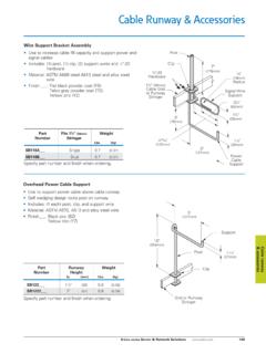
2 Diameter Ratio Larger diameter innerduct may be required for Cable blowing Direct buried installation Recommend smooth-wall or ribbed innerduct (not corrugated) Distribution networks: minimum ID = inches Long haul networks: minimum ID = inchesCable Diameter Ratio= Diameter RatioCable ODCable ODInnerduct IDInnerduct IDCable Lubricants Recommended Polywater (American Polywater Corp.) Hydralube Blue (Arnco) or equivalent Quantity Based on Cable installation length Follow manufacturer s recommendations Do not use detergents (soaps) May cause stress cracking of Cable jacketCable Installation Equipment- Capstan Winch Hydraulic motor used to drive a capstan Typical pulling speeds ~ 75 150 fpm Typical pulling distances ~ 1000 2500 ftCapstan Winch- Precautions Pressure gauge displays hydraulic pressure not Cable tension Gauge must be calibrated to indicate Cable tension Hydraulic relief valve needs routine calibration to confirm and/or adjust bypass valve at 600 lb tension Maximum Pulling Tension Maximum Rated Cable Load = 600 lb (typical)
3 Maximum installation force must not exceed 600 lb Maximum installation force must be controlled using Calibratedcapstan winches Breakaway swivels Slack Cable loopsControlling Installation Tension- Breakaway Pulling Swivel Attached between pulling tape and Cable grip Separates at 600 lb load Internal pin breaks at rated load Confirm proper load rating of internal pin Should not be pulled over sheaves and/or capstans (may weaken pin)Controlling Installation Tension- Capstan Winch Maintain slack loop on pull-off side of intermediate capstans Prevents additive pulling force of multiple capstans Provides a buffer for adjusting pulling speedsSlack loopSlack loopMinimum Bend RadiusFortex DT cables (loose Fiber designs) Under load (during installation) Rmin= 15 OD No load (after installation) Rmin= 10 OD Note: diameter = 2 radius, therefore Dmin= 30 OD (during installation) Dmin= 20 OD (for storage coils)Controlling Bend Diameter Bend diameter is controlled by Using correct diameter capstans Using correct diameter Cable sheaves Forming Cable storage loops in correct diameterCable Storage in HandholeWMinimum inside dimension of hole mustbe large enough to allow slack coils to bestored without violating the minimumrecommended slack coil bend diameterfor slack storage.
4 D >=20 x Cable ODSplice CaseD Cable Installation Equipment- Blowing / Jetting Machines Use compressed air to blow Cable and drive wheels/belt to push Cable Typical installation speeds ~ 150 - 200 fpm Typical installation distances ~ 3,000 ft Requires airtight innerduct couplingsBlowing / Jetting Machines- Precautions Conduct Cable slip test per equipment manufacturer s instructions Conduct Cable buckling test per equipment manufacturer s instructions Observe maximum operating pressures Use proper innerduct inserts & seals Use proper Cable inserts & seals Confirm integrity of innerduct and couplers Clean and lubricate innerductCable Installation Techniques Single Pull Backfeed Technique Forward Feed Technique Intermediate AssistSingle Pull Install entire Cable from splice location to splice location in one continuous operationMH 3MH 4 Figure-8 Method Used to increase distance between splice points Used when Cable length exceeds equipment availability Backfeeds Forward feedsFigure-8 Method- Precautions When figure 8-ing large heavy cables.
5 Use the Smear Method for stacking the Cable layers Offset the cross-over points in each layer by about 4 inches This will help prevent sheath dents caused by the Cable s own weight Limit the height of the figure-8 stack to 2 ftFigure-8 MethodStandard Figure-8 Smeared Figure-8 Figure-8 Eliminator Machines Figure-8 Eliminator machines are used to automate the figure-8 process Equipment may cause Fiber and/or Cable damage and is NOT recommended for use with OFS cableCable subjected to a Cable subjected to a combination of tension, combination of tension, bending, and twistingbending, and twistingBackfeed Placement Position Cable reel near mid-point of Cable route Install first half of the Cable using standard techniquesMH 3MH 5MH 4 Backfeed Method (cont.) Remove remaining Cable from reel and figure-8MH 5MH 4 Cable Backfeed (cont.) Access inside end and feed in opposite direction Install remaining Cable from figure-8 stack to splice locationMH 4MH 3MH 5 Forward Feed Method Pull slack Cable to intermediate manhole Figure-8 slack Cable on groundMH 4MH 3 Forward Feed Method (cont.)
6 Flip figure-8 stack to access Cable end Pull Cable to splice location Can use multiple forward feeds if requiredMH 3MH 5MH 4 Intermediate Assist Use two or more winches to distribute the installation forceIntermediate AssistCable Coiling Use proper coiling methods to prevent excessive Cable twist and Cable damage Observe minimum storage coil diameter Recommended coiling methods Fold-over method Teardrop method Garden Hose methodSummary Maximum Pulling Tension = 600 lb Minimum Bend Radius (Fortex DT Cable ) During Installation: 15 OD After Installation: 10 OD Use of Cable jetting/blowing equipment is recommended Maintain slack loops at capstan winch Use of Figure-8 Eliminator machines is not recommended and Will Void Cable Warranty Eliminate Cable twist with proper coiling methodsAerial Plant Design Aerial Cable plant must be designed to meet NESC storm-load requirements Ensure public safety Prevent aerial plant from falling down Requires a strength design (does not consider Fiber stress) Fiber - Optic Cable plant must also be designed to limit the maximum Fiber stress Ensure long-term reliability of the optical fibers Select support strand and span length to limit the Fiber stress to acceptable levels Requires a stiffness design (usually the limiting design)
7 NESC Storm-Load DistrictsNESC Storm Load ConditionsNESC Ice, Wind, and Temperature Load ConditionsSTORM-LOAD DISTRICTENVIRONMENTAL CONDITIONHEAVYMEDIUMLIGHTR adial Thickness of inch0 Horizontal Wind Pressure4 lb/sq-ft4 lb/sq-ft9 lb/sq-ftTemperature0 F+15 F+30 FConstant to be lb/ftFiber Stress Storm-Load ConditionsIce, Wind and Temperature Conditions Usedfor the Stiffness Design of Aerial Fiber - Optic CableSTORM-LOAD DISTRICTENVIRONMENTAL CONDITIONHEAVYMEDIUMLIGHTALLR adial Thickness of inch00 Horizontal Wind Pressure4 lb/sq-ft4 lb/sq-ft9 lb/sq-ft0 Temperature+32 F+32 F+100 F+170 FMaximum Recommended Span LengthsSTORM LOAD DISTRICTSUPPORT MESSENGERHEAVYMEDIUMLIGHTF ortex DT Loose Tube Cables 1/4 inch EHS 400 ft800 ft900 ftPre-Construction Planning Determine Splice Locations Insure that the splice location is accessible Plan splice locations at corner poles to simplify Cable installation Determine Cable Lengths Include slack Cable for splicing Determine the length and quantity of maintenance coils Determine the Installation Method Stationary Reel Method Moving Reel MethodAerial Cable Placing- Tools & MaterialsAerial Line Truck or Bucket TruckCable Trailer or Reel CarrierCable WinchAerial
8 Cable Placing- Tools & MaterialsCable Stringing BlocksCable GuideRadiosAerial Cable Placing- Tools & MaterialsPull RopePulling GripPulling SwivelSnow ShoesAerial Cable Placing- Tools & MaterialsCable LasherLashing wireLashing Wire ClampsStationary Reel Method WINCHCABLE BLOCKSROPE PULLING GRIP &BREAKAWAY SWIVEL QUADRANT BLOCK STRANDCOMMUNICATIONCOMMUNICATIONS tationary Reel Cable blocks on pole pull rope through Cable Cable through Cable blocks Observe maximum Cable tension Observe minimum bend radius of Cable to support messengerStationary Reel Method- Precautions Use sufficient number of stringing blocks to support the weight of the Cable Use a Cable guide to support the Cable at the messenger Use adequately sized Cable blocks at corner poles Use non-metallic pull rope Use tension-limiting pull winch (or break-away swivel) Pull Cable at a safe, steady speed to avoid surging Maintain constant radio communicationsAerial Installation Methods- Moving Reel Method Cable reel driven along pole line, Cable lifted up to strand and lashed in a one-step installation Does not require Cable blocks or pull lines Most efficient placing methodMoving Reel Method- Precautions Must have unobstructed access to support messenger Position reel carrier 30 to 50 ft in front of Cable lasher Keep reel carrier closely aligned with support messenger Do not feed Cable through roller fairlead (aerial line truck only) Monitor reel rotation and prevent surge Do not use brake on Cable reelSlack Storage- Snow ShoesSlack Storage- Storage CoilsQuestions?
9 For further information, please contactHoward Or visit our website Or call OFS Customer Care1-888- Fiber -HELP (888-342-3743)(1-770-798-5555 from outside the USA)