Transcription of OTIS LINK Escalator Layout and Spec ficat ons …
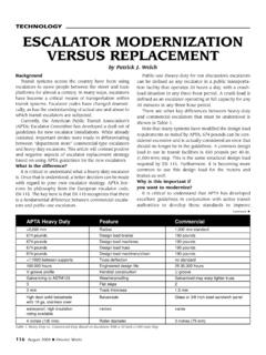
1 Escalator Layout and Speci cations OTIS LINK. Escalator Layout and Speci cations Escalator Layout HOOK OR HOLE IN SLAB. +40. BEAM TO BEAM D=( x H + X) 0 (30 ). D=( x H + X) +40 (35 ). E +20 0 F +20. 0 0. WELL RAIL BY OTHERS. PP. B. 1147 *. 997. 84. 2. 98. min. 2300. AK. 2. H. PP. mi a n. 60. A. 997. AL. Otis reserves the right to change any part of these speci cations without prior notice. Otis LINK 12/06 PPR. A B min min. 60. min. 500. MIN 500mm OTHERWISE DEFLECTOR. 2000. CLEAR FLOOR ACCESS AREA. 2xK. K. 2500. 2000 <5000 <5000 2000. D. Minimum clear floor access area in front of the landings measured from newel end: x Escalator width (K). or x twice Escalator width (K). Remarks: (*) For drive machine Type EC-H2 only. Max. allowable cladding weight 20kg/m2. = Working Point 1 of 2. Escalator Layout and Speci cations OTIS LINK. Escalator Layout and Speci cations Escalator Layout Speci cations P min J.
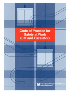
2 125. K. 40 200. FLOOR LINE. 125. STEP STEP. N. CL. 200 40. +40. D 0. Technical Parameters a = 30 . 930. 1000 1630 1011 1208 1550 D + D + 1000. 2572 2849 5452 H + 5452 + R. 930. 3 800 2800 4700 1430 808 1005 1347 2603 D + D + 1000. 930 WITH. 600 3072 1230 605 802 1144 3349 5952 H + 5952 + R D + D + MAINTENANCE. 1000. ROOM IN LOWER. 930. 1000 1630 1011 1208 1550 D + D + AND UPPER. 1000 LANDING. 2172 2449 4652 H + 4652 + R. 930. 2 800 2400 4300 1430 808 1005 1347 2203 D + D + 1000. 930. 600 2672 1230 605 802 1144 2949 5152 H + 5152 + R D + D + 1000. PP AL AK min AB P min N K J F+20 E+20 X D+40 ** B A. FLAT. STEPS TYPE ARRANGEMENT. (kg) (mm) (m) (kg). a = 35 . 930. 1000 1630 1011 1208 1550 D + D + 1000. 2549 2877 5547 H + 5547 + R. 930. 3 800 2918 4500 1430 808 1005 1347 2670 D + D + 1000. 930 WITH. 600 3049 1230 605 802 1144 3377 6047 H + 6047 + R D + D + MAINTENANCE. 1000.
3 ROOM IN LOWER. 930. 1000 1630 1011 1208 1550 D + D + AND UPPER. 1000 LANDING. 2149 2477 4747 H + 4747 + R. 930. 2 800 2518 4100 1430 808 1005 1347 2270 D + D + 1000. 930. 600 2649 1230 605 802 1144 2977 5247 H + 5247 + R D + D + 1000. PP AL AK min AB P min N K J F+20 E+20 X D+40 ** B A. FLAT. STEPS TYPE ARRANGEMENT. (kg) (mm) (m) (kg). Remarks: For formula of D+40, R is the value of truss extension. For formula of A/B, D is in (m). (**) If truss extension, typhoon or seismic zone needs to be considered, please contact your local Otis of ce. 2 of 2.