Transcription of Outlet Structures T-12 - UDFCD
1 Outlet Structures T-12 November 2015 Urban Drainage and Flood Control District OS-1 Urban Storm Drainage Criteria Manual Volume 3 Designing for Maintenance Rather than using the minimum criteria, consider maximizing the width of the trash rack to the geometry of the Outlet . This will reduce clogging and frequency of maintenance. Reduced clogging in EDB Outlet Structures will preserve the initial surcharge volume thus reducing frequency of inundation in the bottom of the basin. This will benefit the grasses and reduce long-term EDB maintenance requirements (including sediment removal in the grassed area) and may reduce the life-cycle cost of the BMP. Description This section provides guidance and details for Outlet Structures for the use primarily with BMPs utilizing sedimentation, ( , extended detention basins, retention ponds and constructed wetland ponds).
2 The information provided in this section includes guidance for different size watersheds as well as for incorporating full spectrum detention as described in the Storage chapter of Volume 2. The details contained in this fact Sheet are intended to provide a starting point for design. UDFCD recommends that design details for Outlet Structures be specific for each site with structural details drawn to scale. The details provided in this fact Sheet are not intended to be used without modification or additional detail. Outlet Design Large Watershed Considerations UDFCD recommends that water quality treatment be provided close to the pollutant source. This is a fundamental concept of Low Impact Development (LID).
3 Although flood control facilities, including full spectrum detention facilities, have been shown to be very effective for watersheds exceeding one square mile, this is not the case for water quality facilities. One reason for this is that the baseflow associated with a larger watershed will vary and can be difficult to estimate. The orifice plate should be designed to pass the baseflow while detaining the water quality capture volume (WQCV) for approximately 40 hours. When the baseflow is overestimated, the WQCV is not detained for the recommended time, passing through without treatment. When the baseflow is underestimated, the elevation of the permanent pool will be higher than designed, causing maintenance issues as well as reducing the volume available for detention of the WQCV, which also allows for a portion of this volume to pass through without treatment.
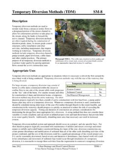
4 For this reason, UDFCD recommends that facilities designed for both water quality and flood control be limited, where possible, to watersheds without a baseflow. The maximum recommended watershed for combined facilities is one square mile. Additional discussion on designing for baseflows is provided in the EDB BMP fact Sheet (T-5). Photograph OS-1. Although each site is different, most sedimentation BMPs have similar Outlet Structures . Each structure should include a partially submerged orifice plate with a screen (or grate) protecting the orifice plate from clogging, and an overflow weir for flows exceeding the WQCV or excess urban runoff volume (EURV), when full spectrum detention is used.
5 T-12 Outlet Structures OS-2 Urban Drainage and Flood Control District November 2015 Urban Storm Drainage Criteria Manual Volume 3 Orifice Plates, Trash Racks, and Safety Grates An orifice plate is used to release the WQCV slowly over 40 hours. For full spectrum detention , the orifice plate is extended to drain a larger volume, the EURV, over approximately 72 hours. The figures and tables in this section provide recommendations for orifice configurations and trash rack type and size. Guidance is provided for plates using both circular and rectangular orifices. Orifice Sizing Follow the design steps included in the BMP fact Sheet for the appropriate BMP. The UD- detention workbook, available at , can be used to route flows and calculate the required orifice sizes.
6 UDFCD recommends a total of three orifices to maximize the orifice size and avoid clogging of the orifice plate. A detail showing the recommended orifice configuration is provided in Figure OS-4. Trash Rack Sizing Once the size of the orifice has been determined, this information, along with the total orifice area in the water quality plate, is used to determine the total open area of the grate. See Figure OS-1 and use the dashed line to size the trash rack. Include the portion of the trash rack that is inundated by the micropool in total open area of the grate. Be aware, Figures OS-5, OS-6, OS-7, and OS-8 dimension the minimum width clear for the trash rack frame.
7 It is also important to provide adequate width for attachment to the Outlet structure (see Photos OS-2 and OS-3) . Also, consider maximizing the width of the trash rack to the geometry of the Outlet . This will reduce clogging and maintenance requirements associated with cleaning the trash rack. This fact Sheet also includes recommendations for the thickness of the steel water quality plate (see Table OS-2). Photograph OS-2. This trash rack could not be properly Photograph OS-3. Trash rack after repair. Outlet Structures T-12 November 2015 Urban Drainage and Flood Control District OS-3 Urban Storm Drainage Criteria Manual Volume 3 Safety Grates Safety grates are intended to keep people and animals from inadvertently entering a storm drain.
8 They are sometimes required even when debris entering a storm drain is not a concern. The grate on top of the Outlet drop box is considered a safety grate and should be designed accordingly. The danger associated with Outlet Structures is the potential associated with pinning a person or animal to unexposed Outlet pipe or grate. See the Culverts and Bridges chapter of Volume 2 of this manual for design criteria related to safety grates. Figure OS-1. Trash Rack Sizing At / Aot = At / Aot = 11010004812162024283236404448 Ratio of Total Grate Open Area to Total Outlet Area At / Aot Outlet Diameter or Minimum Dimension D (Inches) Safety GratesTrash RacksD>24"4 T-12 Outlet Structures OS-4 Urban Drainage and Flood Control District November 2015 Urban Storm Drainage Criteria Manual Volume 3 Outlet Geometry Outlets for small watersheds will typically be sized for maintenance operations while the geometry of outlets for larger watersheds may be determined based on the required size of the trash rack.
9 For all watershed sizes, the Outlet should be set back into the embankment of the pond to better allow access to the structure. This also provides a more attractive BMP. For larger watersheds, this will require wing walls. Wing walls are frequently cast-in-place concrete, although other materials, such as grouted boulders, may be used where appropriate. Consider safety, aesthetics, and maintenance when selecting materials and determining the geometry. A safety rail should be included for vertical drops of 3 feet or more. Depending on the location of the structure in relation to pedestrian trails, safety rails may also be required for lesser drops. Stepped grouted boulders can be used to reduce the height of vertical drops.
10 As shown in Figures EDB-1 and EDB-2 provided in BMP fact Sheet T-5, wing walls can be flared or parallel. There are advantages to both configurations. Parallel wing walls may be more aesthetic; however, depending on the geometry of the pond, may limit accessibility to the trash rack. Flared wing walls can call attention to the structure but provide better accessibility and sometimes a vertical barrier from the micropool of an EDB, which can increase safety of the structure. Parallel walls can also be used with a second trash rack that is secured flush with the top of the wall as shown in Photo OS-4. This eliminates the need for a safety rail and may provide additional protection from clogging; however, it creates a maintenance issue by restricting access to the water quality screen.