Transcription of Output Circuit & Connection Diagram
1 3334 Output Circuit & Connection Diagram General DataCurrent Consumption Application HintsWhen using a switching regulator , please be sure to ground the FG ( Frame Ground ) and G ( Ground ) terminal , If failure to do so , if may resulting malfunction of the sensor for the noise of the switching regulator. The ripple of the DC power supply is required less than 20% to avoid resulting malfunction of the Voltage< 10 m/ CNPNPNPSCR<10% of Sensing Distance100mA max.< 2mA< max.< 10mA< CurrentResidual Voltage< TypeSpecificationAC Type10~30 VDC90~250 VAC50/60Hz< 20% of Peak to PeakWiring MethodColor of Sensing FacePower RippleOutput CurrentProtection CircuitOperating ClassHysteresisThermal DriftVoltage Drift< 1 m/VShort Circuit &Polarity Reversed ProtectionSurge Protection CircuitIP-673 Cores / X 2m2 Cores / X 2mNPN : Red ;PNP ;GreenBlue-20 C~+80 C.
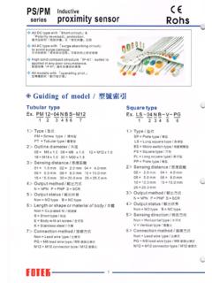
2 35%~95% RH1> TYPE PS=SQUARE TYPE PP=PLATE TYP PL=LONG TYPE BS=MICRO TYPE2> SENSING DISTANCE 04= mm 10= 05= mm 15= mm3> Output METHOD N= NPN P= PNP4> Output STATUS NON= NO TYPE B= NC TYPE B= NC TYPE5> DIRECTION OF SENSING V= VERTICAL TYPE NON= HORIZONTAL TYPE 6> Connection METHOD NON= LEAD WIRE TYPE PG= M 8 L EAD W IRE C ONNECTOR T YPEINDUCTIVE PROXIMITY SENSORPS/PMseries series DC T YPE W ITH S HORT C IRCUIT P ROTECTION A ND POLARITY REVERSED PROTECTION AC TYPE WITH SURGE ABSORBING Circuit MAY AVOID SURGE DAMAGED HIGH SOLID COMPACT STRUCTURE IP-67 SUITED TO BE APPLIED IN THE POOR CIRCUMSTANCE IP67- ALL MODELS WITH OPERATIN LED, EASY TO ADJUSTED Guiding of Model Ex.
3 PM - 12 04 - N - B S TUBULAR TYPETUBULAR TYPEM1277 SQUARE TYPESQUARE TYPEEx. LS - 04 N - B V PG1> TYPE PM= SCREW TYPE 2> OUTLINE DIAMETER 08= 18= 12= 30= 3> SENSING DISTANCE 02= mm 10=10. mm 05= mm 15= mm4> Output METHOD N=NPN P=PNP S=SCR5> Output STATUS NON= NO TYPE B= NC TYPE B= NC TYPE6> LENGTH OF BODY NON= STANDARD TYPE S= SHORT TYPE7> CONNECTING METHOD NON= LEAD WIRE TYPE M12= M12 CONNECTOR TYPE NOTETHE B<NC> TYPE HAVE NO STOCKMAYBE,ACCEPTED ORDER TO MANUFACTURE134134 - PG= M 8 L EAD W IRE C ONNECTOR T YPE - 3334 Output Circuit & Connection Diagram General DataCurrent Consumption Application HintsWhen using a switching regulator , please be sure to ground the FG ( Frame Ground ) and G ( Ground )
4 Terminal , If failure to do so , if may resulting malfunction of the sensor for the noise of the switching regulator. The ripple of the DC power supply is required less than 20% to avoid resulting malfunction of the Voltage< 10 m/ CNPNPNPSCR<10% of Sensing Distance100mA max.< 2mA< max.< 10mA< CurrentResidual Voltage< TypeSpecificationAC Type10~30 VDC90~250 VAC50/60Hz< 20% of Peak to PeakWiring MethodColor of Sensing FacePower RippleOutput CurrentProtection CircuitOperating ClassHysteresisThermal DriftVoltage Drift< 1 m/VShort Circuit &Polarity Reversed ProtectionSurge Protection CircuitIP-673 Cores / X 2m2 Cores / X 2mNPN : Red ;PNP ;GreenBlue-20 C~+80 C ; 35%~95% RH1> TYPE PS=SQUARE TYPE PP=PLATE TYP PL=LONG TYPE BS=MICRO TYPE2> SENSING DISTANCE 04= mm 10= 05= mm 15= mm3> Output METHOD N= NPN P= PNP4> Output STATUS NON= NO TYPE B= NC TYPE B= NC TYPE5> DIRECTION OF SENSING V= VERTICAL TYPE NON= HORIZONTAL TYPE 6> Connection METHOD NON= LEAD WIRE TYPE PG= M 8 L EAD W IRE C ONNECTOR T YPEINDUCTIVE PROXIMITY SENSORPS/PMseries series DC T YPE W ITH S HORT C IRCUIT P ROTECTION A ND POLARITY REVERSED PROTECTION AC TYPE WITH SURGE ABSORBING Circuit MAY AVOID SURGE DAMAGED HIGH SOLID
5 COMPACT STRUCTURE IP-67 SUITED TO BE APPLIED IN THE POOR CIRCUMSTANCE IP67- ALL MODELS WITH OPERATIN LED, EASY TO ADJUSTED Guiding of Model Ex. PM - 12 04 - N - B S TUBULAR TYPETUBULAR TYPEM1277 SQUARE TYPESQUARE TYPEEx. LS - 04 N - B V PG1> TYPE PM= SCREW TYPE 2> OUTLINE DIAMETER 08= 18= 12= 30= 3> SENSING DISTANCE 02= mm 10=10. mm 05= mm 15= mm4> Output METHOD N=NPN P=PNP S=SCR5> Output STATUS NON= NO TYPE B= NC TYPE B= NC TYPE6> LENGTH OF BODY NON= STANDARD TYPE S= SHORT TYPE7> CONNECTING METHOD NON= LEAD WIRE TYPE M12= M12 CONNECTOR TYPE NOTETHE B<NC> TYPE HAVE NO STOCKMAYBE.
6 ACCEPTED ORDER TO MANUFACTURE134134 - PG= M 8 L EAD W IRE C ONNECTOR T YPE - 3536PS Square Type Plastic HousingOutputSensingMountingSensingOpera ting ~ 30 VDC10 ~ 30 VDCH orizontalHorizontalVerticalVerticalVerti cal500HZ20 HZINDUCTIVE PROXIMITY SENSOR800HZ2 KHZ800HZ800 HZHorizontal10 ~ 30 VDC10 ~ 30 VDC10 ~ 30 VDC10 ~ 30 VDC10 ~ 30 VDC90 ~ DimensionModel2 KHZ10 ~ M8/M12 Tubular TypePM08/PM12series ~ 30 VDC10 ~ ~ 30 VDC10 ~ 30 VDC10 ~ 30 VDC10 ~ 30 VDC90 ~ 250 VAC90 ~ 250 VACNon-FlushedFlushedNon-FlushedFlushedN on-FlushedFlushedOutline ~ 30 VDCF lushedNon-FlushedOutputStatusOutputMetho dOperatingVoltageSensingDirectionRespons eFrequencyMountingMethodPM08-01 NPM08-01 NBPM08-01 PPM08-01 PBPM08-02 NPM08-02 NBPM08-02 PPM08-02 PBPM12-02N-SPM12-02P-SPM12-04N-SPM12-04P -SPM12-02 NPM12-02 NBPM12-02 PPM12-02 PBPM12-04 NPM12-04 NBPM12-04 PPM12-04 PBPM12-02 SPM12-02 SBPM12-04 SPM12-04 SBNONCNONCNONCNONCNONCNONCNONCNONCNONCNO NCNONCNONCNONCNONCNPNPNPNPNPNPNPNPNPSCRS CRNPNPNPNPNPNPNPNPNPPM12-02N-M12 NONCNONCPM12-02NB-M12PM12-02P-M12PM12-02 PB-M12PM12-04N-M12PM12-04P-M12PM12-04NB- M12PM12-04PB-M12 NONCNONCNPNPNPNPNPNP10 ~ ~ 250 VACNon-Flushed3536PS Square Type Plastic HousingOutputSensingMountingSensingOpera ting ~ 30 VDC10 ~ 30 VDCH orizontalHorizontalVerticalVerticalVerti cal500HZ20 HZINDUCTIVE PROXIMITY SENSOR800HZ2 KHZ800HZ800 HZHorizontal10 ~ 30 VDC10
7 ~ 30 VDC10 ~ 30 VDC10 ~ 30 VDC10 ~ 30 VDC90 ~ DimensionModel2 KHZ10 ~ M8/M12 Tubular TypePM08/PM12series ~ 30 VDC10 ~ ~ 30 VDC10 ~ 30 VDC10 ~ 30 VDC10 ~ 30 VDC90 ~ 250 VAC90 ~ 250 VACNon-FlushedFlushedNon-FlushedFlushedN on-FlushedFlushedOutline ~ 30 VDCF lushedNon-FlushedOutputStatusOutputMetho dOperatingVoltageSensingDirectionRespons eFrequencyMountingMethodPM08-01 NPM08-01 NBPM08-01 PPM08-01 PBPM08-02 NPM08-02 NBPM08-02 PPM08-02 PBPM12-02N-SPM12-02P-SPM12-04N-SPM12-04P -SPM12-02 NPM12-02 NBPM12-02 PPM12-02 PBPM12-04 NPM12-04 NBPM12-04 PPM12-04 PBPM12-02 SPM12-02 SBPM12-04 SPM12-04 SBNONCNONCNONCNONCNONCNONCNONCNONCNONCNO NCNONCNONCNONCNONCNPNPNPNPNPNPNPNPNPSCRS CRNPNPNPNPNPNPNPNPNPPM12-02N-M12 NONCNONCPM12-02NB-M12PM12-02P-M12PM12-02 PB-M12PM12-04N-M12PM12-04P-M12PM12-04NB- M12PM12-04PB-M12 NONCNONCNPNPNPNPNPNP10 ~ ~ 250 VACNon-FlushedPolymid HousingPolymid Housing3738 M30 Tubular Type Fixed BracketPM30PM18 M18 Tubular TypeINDUCTIVE PROXIMITY SENSOR series 800 HZFlushedNon-Flushed10 ~ 30 VDC10 ~ 30 VDC800HZ800HZ20HZ10 ~ 30 VDC10 ~ 30 VDC10 ~ 30 VDC90 ~ 250 VAC90 ~ 250 VACNon-FlushedNon-FlushedOutline DimensionModel800HZ10 ~ 30 VDCF
8 LushedNon-FlushedOutputStatusOutputMetho dOperatingVoltageSensingDirectionRespons eFrequencyMountingMethodPM18-05N-SPM18-0 5NB-SPM18-05P-SPM18-05PB-SPM18-08N-SPM18 -08NB-SPM18-08P-SPM18-08PB-SPM18-05 NPM18-05 PPM18-08 NPM18-08 PPM18-08N-PPM18-08NB-PPM18-08P-PPM18-08P B-PPM18-08S-PPM18-08SB-PPM18-05 SPM18-05 SBNONCNONCNONCNONCNONCNONCNONCNONCNONCNO NCNONCNONCNONCNPNPNPNPNPNPNPNPNPSCRSCRNP NPNPNPNPNPNONCNONCNONCNONCNPNPNPNPNPNP10 ~ ~ ~ ~ 30 VDC10 ~ 30 VDC500HZ10 ~ 30 VDCO utline DimensionModel500HZ10 ~ 30 VDCF lushedNon-FlushedOutputStatusOutputMetho dOperatingVoltageSensingDirectionRespons eFrequencyMountingMethodPM30-10N-SPM30-1 0NB-SPM30-10P-SPM30-10PB-SPM30-15N-SPM30 -15NB-SPM30-15P-SPM30-15PB-SPM30-10 NPM30-10 PPM30-15 NPM30-15 PNONCNONCNONCNONCNONCNONCNONCNONCNPNPNPN PNPNPNPNPNPNPNPNPPM30-15 NBPM30-10 ~ 250 VAC90 ~ HousingPolymid Housing3738 M30 Tubular Type Fixed BracketPM30PM18 M18 Tubular TypeINDUCTIVE PROXIMITY SENSOR series 800 HZFlushedNon-Flushed10 ~ 30 VDC10 ~ 30 VDC800HZ800HZ20HZ10 ~ 30 VDC10 ~ 30 VDC10 ~ 30 VDC90 ~ 250 VAC90 ~ 250 VACNon-FlushedNon-FlushedOutline DimensionModel800HZ10 ~ 30 VDCF
9 LushedNon-FlushedOutputStatusOutputMetho dOperatingVoltageSensingDirectionRespons eFrequencyMountingMethodPM18-05N-SPM18-0 5NB-SPM18-05P-SPM18-05PB-SPM18-08N-SPM18 -08NB-SPM18-08P-SPM18-08PB-SPM18-05 NPM18-05 PPM18-08 NPM18-08 PPM18-08N-PPM18-08NB-PPM18-08P-PPM18-08P B-PPM18-08S-PPM18-08SB-PPM18-05 SPM18-05 SBNONCNONCNONCNONCNONCNONCNONCNONCNONCNO NCNONCNONCNONCNPNPNPNPNPNPNPNPNPSCRSCRNP NPNPNPNPNPNONCNONCNONCNONCNPNPNPNPNPNP10 ~ ~ ~ ~ 30 VDC10 ~ 30 VDC500HZ10 ~ 30 VDCO utline DimensionModel500HZ10 ~ 30 VDCF lushedNon-FlushedOutputStatusOutputMetho dOperatingVoltageSensingDirectionRespons eFrequencyMountingMethodPM30-10N-SPM30-1 0NB-SPM30-10P-SPM30-10PB-SPM30-15N-SPM30 -15NB-SPM30-15P-SPM30-15PB-SPM30-10 NPM30-10 PPM30-15 NPM30-15 PNONCNONCNONCNONCNONCNONCNONCNONCNPNPNPN PNPNPNPNPNPNPNPNPPM30-15 NBPM30-10 ~ 250 VAC90 ~ Connecting Method of AND & OR Basic Definition of Inductive Proximity SensorTargetWhich is steel , 1 mm thick ness , square form withwidth lengths equal to the diameter of the sensing surface , if the target is made of a different material , the sensing distance must be multiplied by the Correction Factors.
10 Accuracy < Repetition >Tolerance of operating position that sensor is certainly operated under the same conditions .HysteresisHysteresis is the different distance between theoperating points that the target is approachingand leaving the sensing area of the sensor , Thevalue is expressed as a percentage of the sensing distance , < d/Sn% > .Switch frequencyThis is the maximum response frequency persecond , based on a pulse / pause ratio of1:2 . The sketch shows the condition of test .INDUCTIVE PROXIMITY SENSOR How To Install Induction Proximity SensorFlushed typeA proximity sensor can be flushed mounted inmetal and surrounded by metal up to the level ofthe active face. d : diameter Sn : sensing dista