Transcription of Overview of OLED Display Technology
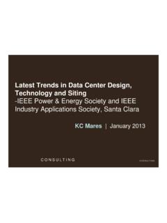
1 Overview of OLED Display Technology Homer Antoniadis, Product Development Group Manager phone: (408) 456-4004. cell: (408) 314-6460. email: Homer Antoniadis | OLED Product Development|. page:1. Outline ! OLED device structure and operation ! OLED materials (polymers and small molecules). ! Evolution of OLED performance ! OLED process and fabrication technologies ! Color capabilities ! White emitting OLEDs ! Passive and active matrix driving schemes ! OLED market potential ! Products and demonstrators Homer Antoniadis | OLED Product Development|. page:2. OLED Display and Pixel structure Display Pixel Cover glass Cathode Cathode (Ba,Ca/Al 2000 ).
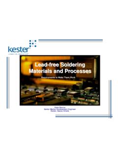
2 Emissive polymer layer Emissive polymer layer ~ 800 . Conducting Conducting polymer layer polymer layer ~ 1200 . Epoxy Anode (ITO 1500 ). Anode Single pixel structure Glass substrate Human hair is 200X the thickness of the OLED layers Homer Antoniadis | OLED Product Development|. page:3. OLED Device Operation Principles OLEDs rely on organic materials (polymers or small molecules) that give off light when tweaked with an electrical current _ _ _ _ _ _ _. Cathode ! Electrons injected from cathode Emissive polymer _+ _+ _ _ ! Holes injected from anode V ! Transport and radiative recombination of electron hole + + + pairs at the emissive polymer Conducting polymer + + + + + ++ +.
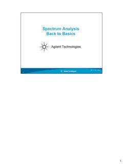
3 Anode +. OLED device operation (energy diagram). Conducting Cathode- Emissive polymer Transparent polymer layer (s). light substrate Anode (ITO). LUMO e - - e LUMO. Light HOMO. h+ h+. HOMO. h+. ca. 100 nm 10 - >100 nm <100 nm >100 nm Homer Antoniadis | OLED Product Development|. page:4. Optoelectronic Device Characteristics Luminance-Current-Voltage Efficiency-Luminance-Voltage 10. 0. 12 12. -1. 10 10. Current Density (A/cm ). 2. 10. Efficiency (cd/A). -2. 10. Efficiency (cd/A). 8. 10. -3. 8. -4 6. 10. 6. 10. -5. 4. 10. -6 4. 2. -7. 10. 2 0. -8 -6 -4 -2 0 2 4 6 8 10 100 1000 10000 0 2 4 6 8.
4 2. Voltage (Volts) Luminance (cd/m ) Voltage (V). 5. 10. 4. LUMINANCE is the luminous intensity per unit 10. area projected in a given direction Luminance (cd/m ). 2. 3. 10. The SI unit is the candela per square meter 10. 2. (cd/m2), which is still sometimes called a nit 1. 10. The footlambert (fL) is also in common use: 10. 0. 1 fL = cd/m2. -1. 10 0 2 4 6 8. Voltage (Volts). Homer Antoniadis | OLED Product Development|. page:5. Evolution of LED Performance SM OLED. Polymer OLED. Courtesy of Agilent Technologies Homer Antoniadis | OLED Product Development|. page:6. Electroluminescent Polymers Conducting polymers !
5 Polyaniline (PANI:PSS) NH. ! Polyethylenedioxythiophene (PDOT:PSS) PANI PDOT PSS. Emissive polymers R1. ! Polyphenylenevinylene (R-PPV). ! Polyfluorene (PF) R1. n n R1 R1. R-PPV. Processed by : PF. Spin casting, Printing, Roll-to-roll web coating IP owned by Cambridge Display Technology Homer Antoniadis | OLED Product Development|. page:7. Multiple emission colors achieved by Covion Different emission colors can be obtained with a variety of chemical structures 300 nm 500 nm 700 nm PPP. n PPV. OR. CN. PT or S. CN-PPV RO. Homer Antoniadis | OLED Product Development|. page:8.
6 Multiple emission colors achieved by Dow Chemical n R1 R 1. PF. Homer Antoniadis | OLED Product Development|. page:9. Polymer OLED Display fabrication steps Deposit and pattern anode (ITO). Pattern polymer layers (first conducting then emissive). Spin coating Ink Jet printing Screen printing Web coating Vacuum deposit and pattern cathode (Ba,Ca/Al). Homer Antoniadis | OLED Product Development|. page:10. Ink Jet Printing to Pattern Polymers (Full Color Applications). Ink Jet Head Red Green Blue emitter emitter emitter Substrate Ink Jet printing to define and pattern R, G, B emitting subpixels Homer Antoniadis | OLED Product Development|.
7 Page:11. The Holy Grail: Flexible OLEDs Sheila Kennedy, Harvard Univ., 1999. Homer Antoniadis | OLED Product Development|. page:12. Electroluminescent Small Molecules Hole transport small molecules ! Metal-phthalocyanines N N. ! Arylamines, starburst amines NPD. Emissive small molecules ! Metal chelates, distyrylbenzenes N. O. ! Fluorescent dyes N Al O. O. N. Processed and deposited by : thermal evaporation in vacuum Alq3. IP owned by Eastman Kodak Homer Antoniadis | OLED Product Development|. page:13. Polymer and Small Molecule Device Structures Small molecule Polymer Cathode - LiF/Al Cathode Ba, Ca/Al ETL - Alq3.
8 ETL - PPV, PF. EML - doped Alq3. HTL - NPB HIL - PDOT, Pani HIL - CuPc Anode - ITO Anode - ITO. Substrate - glass Substrate - glass Multi-layer structure Bilayer structure made all in vacuum made from solution Homer Antoniadis | OLED Product Development|. page:14. Full color patterning with small molecules substrate R emission layer Cathode separator Shadow mask ITO. G emission layer Shadow mask ITO. NPD Alq3. B emission layer Shadow mask ITO. Small molecules are thermally R, G, B pattering is defined by evaporated in vacuum shadow masking in vacuum Homer Antoniadis | OLED Product Development|.
9 Page:15. White emitting small molecule OLEDs Homer Antoniadis | OLED Product Development|. page:16. Phosphorescent small molecule OLEDs PHOLED Technology offers significant room for further performance advances Homer Antoniadis | OLED Product Development|. page:17. The Head-Start of Small Molecule OLEDs ! Manufacturing started ! Pioneer 1997. ! TDK (Alpine, 2001). ! Samsung-NEC Mobile Display (SNMD) (2002). ! RiTdisplay (2003). ! Sanyo-Kodak (2003). ! R, G, B colors available ! limited lifetimes for blue ! Shadow masking allows easy patterning for area color ! presents challenges with scalability and high volume manufacturing !
10 Shadow masking challenging for full color ! high throughput and scalability is a challenge Homer Antoniadis | OLED Product Development|. page:18. Advantages of Solution Processing (Polymer) OLEDs ! Lower fabrication cost ! fewer vacuum deposition steps - lower capital cost ! advantageous materials usage and scalability (I/J printing). ! Solution processing techniques ! compatible with printing techniques - lower cost for full color ! scalable to very large substrates (high volume manufacturing). ! better mechanical integrity ! compatible with roll process for flex manufacturing Homer Antoniadis | OLED Product Development|.