Transcription of Steward - IEEE
1 StewardEMI Suppression Technical PresentationStewardStewardSlide 1 Steward EMI PresentationLee HillFounding PartnerSilent Solutions(603) 578-1842 MeadorsEMI Product ManagerSteward(423) Suppression Technical PresentationStewardStewardSlide 2A. EMI TopicsA. EMI of EMI sources and how to find , broadband and high frequency EMI problems4. Typical & numerous EMI to prevent EMI problems in original EMI challenges for today s products & future productsStewardEMI Suppression Technical PresentationStewardStewardSlide 3B. Review of EMI Topics Related to Magnetics/FerritesB. Review of EMI Topics Related to Magnetics/Ferrites1.
2 Interesting & unique coupling model-How ferrites reduce noise -a) How ferrites reduce noise at the sourceb) How ferrites reduce noise at the you need to design with physical placement of secrets other folks may not tell current and tradeoffs & StewardEMI Suppression Technical PresentationStewardStewardSlide 4C. ApplicationsC. power bus input power sources of EMI in switch-mode power supplies4. Using ferrites to reduce EMI at input and output of and answer + Bring your favorite problemD. Product PresentationD. Product chokes beads/arrays Suppression Technical PresentationStewardStewardSlide 51.
3 Challenges of EMI1. Challenges of EMI Radio frequency emissions from electronic products are regulatedover the frequency range of (at least) 10 KHz to 40 GHz Conducted and radiated emissions limits require noise currents onantenna structures (external cables, external chassis surfaces)and AC, some DC, some signal ports to be <10-5 amps ( )(10 uA)-The majority of electronic devices utilize functional currents of at least 1 mA-Systems must achieve a minimum of 40 dB isolation betweenthe intendedsignals on PCBs, connectors, cables, and the unintendedsignals on antenna structures or power cablingStewardEMI Suppression Technical PresentationStewardStewardSlide 62.
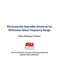
4 2. Typical EMI Sources Typical EMI Sources --What Do They Look Like?What Do They Look Like?freqSpectrum Analyzer Frequency Domain timeOscilloscope Time Domain ToPredictable, periodic,NON-randomsignalsare made up of manylarge(size) frequenciescalled harmonics .These are strongEMI / To3/ TUnpredictable, non-periodic, randomsignals are made up of smaller, wider, fuzzier are weakEMIsourcestime Time Domain Tofreqo1 / To3/ T Frequency Domain StewardEMI Suppression Technical PresentationStewardStewardSlide 72. Typical EMI Sources 2. Typical EMI Sources --What Do They Look Like?What Do They Look Like?Square wave with finite rise time (trapezoidal) Slow edges yield weaker high frequency harmonics A 50 MHz clock is worse than a 75 MHz clock if it has a faster risetime Low-pass filtering in frequency slows the edge rate in time TFundamental Frequency = 1o/A/2 Tor!
5 AAmplitudeTimeTime DomainLog FrequencyAmplitudeFrequency width =Risetime = r1__1__r-20 dB/decade-40 dB/decade StewardEMI Suppression Technical PresentationStewardStewardSlide 82. Typical EMI Sources 2. Typical EMI Sources --How ferrites can help solve the noise problem The series impedance of ferrites can be used to form a portion of a low pass filter at the signal output of an electronic device. In the time domain, the rise andfall times of the base waveform are increased. In the frequency domain, higher frequency signal harmonics are reduced, and so we have a weaker noise source. Low impedance (Z<100 ohm) SMT ferrite beads can be used at a signal output to damp or terminate the oscillations that may otherwise occur on the edges of fast digital signals.
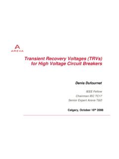
6 Care must be taken not to excessively slow digital signal edge rates. In microprocessor applications, setup and hold times may be violated. In power electronics, power dissipation can be adversely affected. LLOvershoot & oscillations can be reducedogic 1ogic 0dTStewardEMI Suppression Technical PresentationStewardStewardSlide 92. Typical EMI Sources 2. Typical EMI Sources --How to Find ThemHow to Find ThemAn interesting noise problem that we see frequently involvesnoise coupling from high speed silicon ICs with and without heatsinks. Noise is coupled from the IC to nearby antenna structures suchas portions of conductive chassis or wires attached to the SinkC2 StewardEMI Suppression Technical PresentationStewardStewardSlide 102.
7 Typical EMI Sources 2. Typical EMI Sources --How to Find ThemHow to Find ThemIn some cases this noise model can be verified and an economical solution found by taking before and after EMI emissions measurements using the following actionsa) temporarily removing the heatsink, orb) temporarily bonding the heatsink to chassis orPCB signal return, orc) placing a Steward ferrite plate directly on top of the IC or has a relative permitivity greater than air and so cansimultaneously provide magnetic and dielectric Suppression Technical PresentationStewardStewardSlide 113. Low, BB, And High Frequency EMI Problems3.
8 Low, BB, And High Frequency EMI ProblemsOur customers face EMI design challenges that can spanseven decades of frequency! Consider an optical networking systemSMPS@ 400 kHzRef clock @ 9 kHzLogic PCBM emory from 133 to 500+ MHzHigh power laser at or GHzStewardEMI Suppression Technical PresentationStewardStewardSlide 124. Typical EMI Fixes 4. Typical EMI Fixes EMI CANBE REDUCED IN A NUMBER OF WAYS; Move components on the PCB Add or improve return ( ground ) planes Reduce the length of high speed noise source PCB traces Improve signal integrity in noise source circuits by adjusting characteristicimpedance of signal path along PCB traces or wiring, or adding termination components Add filters consisting of inductors, capacitors, resistors, or combinations of these parts.
9 Change active circuit components, lower sink/source current, slower rise/fall times Use special shielding techniquesAdding lossless energy storage components such as inductors and capacitorscan only reflect or redirect EMI, with the possible result of squeezingthe EMI sausage from one frequency to anotherStewardEMI Suppression Technical PresentationStewardStewardSlide 134. Typical EMI Fixes 4. Typical EMI Fixes EMI CANBE REDUCED BY Adding ferrite productsWhen used most effectively, FERRITES will ABSORB the EMI energy,dissipating it as tiny amounts of heat (microwatts)BE SURE TO USE THE RIGHT FERRITE PRODUCTS tewardEMI Suppression Technical PresentationStewardStewardSlide 145.
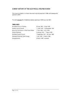
10 Adding a Ferrite Bead to the Decoupling Network, 5. Adding a Ferrite Bead to the Decoupling Network, Using Power Islands Using Power Islands "Gnd"VccICFerriteBeadzProvide a low impedance power bus on/in the PCB for high speed digital logic. Use ferrites to provide filtered power to attenuate conductive coupling from digital noise sources to the larger PCB power planes and attached wireszWhen might it help reduce PCB generated EMI?zWhen might it help increase PCB generated EMI?zWhen might intended circuit function be impaired?StewardEMI Suppression Technical PresentationStewardStewardSlide 156. New EMI challenges for today s products & future products6.