Transcription of OWNER’S MANUAL High Head Centrifugal Pump - …
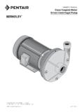
1 OWNER'S MANUAL . high Head Centrifugal Pump SSCX, SSCXS Series 3342 1198 ASB. ODP MOTORS TEFC MOTORS. HP Model Number 115/230/60/1 208-230/460/60/3 115/230/60/1 208-230/460/60/3. 1/2 SS1XN-1 2 B78635 B78636 B78647 B78648. 3/4 SS1XN-3 4 B78637 B78638 B78649 B78650. 3/4 SS1XS-3 4 B82411 B82412 B82413 B82414. 1 SS1XN-1 B78639 B78640 B78651 B78652. 1 SS1XS-1 B82415 B82416 B82417* B82418. 1-1/2 SS1XN-11 2 B78641 B78642 B78653* B78654. 1-1/2 SS1XS-11 2 B82419 B82420 B82421 B82422. 2 SS11 4XN-2 B78643* B78644 B78655* B78656. 2 SS1XS-2 B82423* B82424 B82425* B82426. 2-1/2 SS11 4XN-21 2 B78645* B78646 B78657* B78658. 2-1/2 SS1XS-21 2 B82427* B82428 B82429* B82430. * 230 Volt only. Important For best possible performance and continuous, satisfactory operation, read these instructions before installing your new pump. Should service be required, this MANUAL can be a valuable guide. It should be kept near the installation for ready reference.
2 293 WRIGHT STREET, DELAVAN, WI 53115 PH: 888-782-7483. 2013 Pentair, Ltd. All Rights Reserved. BE495 (Rev. 03/21/13). Safety 2. Important Safety Instructions Risk of explosion. The pump body SAVE THESE INSTRUCTIONS - This MANUAL contains may explode if used to boost pressure above 100 psi important instructions that should be followed during (689 kPa). Do not use this pump with inlet pressure installation, operation, and maintenance of the product. greater than 70 psi (483 kPa). If not already in the Save this MANUAL for future reference. piping system, install a pressure relief valve in the pump This is the safety alert symbol. When you see this discharge line capable of passing the full pump flow at symbol on your pump or in this MANUAL , look for one of 100 psi (689 kPa). If local code requires installation of a the following signal words and be alert to the potential pressure relief valve capable of handling the full pump for personal injury!
3 Flow at a pressure less than 100 psi (689 kPa), follow the code requirements. indicates a hazard which, if not avoided, will result in death or serious injury. Risk of fire or explosion. To avoid risk of fire and explosion, Pump Water Only with this pump. Do indicates a hazard which, if not avoided, not pump salt water, flammable liquids or chemicals. Do could result in death or serious injury. not use the pump near gas pilot lights or where chemical indicates a hazard which, if not avoided, or gas fumes are present. Use of an electric pump with could result in minor or moderate injury. liquids other than water or in an atmosphere containing NOTICE addresses practices not related to chemical or gas fumes may ignite those liquids or personal injury. gases and cause injury or death due to an explosion The manufacturer cannot anticipate every possible and/or fire. circumstance that might involve a hazard. The warnings Burn hazard.
4 If water is trapped in the in this MANUAL , and the tags and decals affixed to the unit pump during operation it may turn to steam. Trapped are, therefore, not all-inclusive. If you use a procedure steam can lead to an explosion and burns. Never run the or operating technique that the manufacturer does not pump with the outlet closed or obstructed. specifically recommend, you must satisfy yourself that it is safe for you and others. You must also make sure that California Proposition 65 Warning the procedure or operating technique that you choose This product and related accessories does not render the system unsafe. contain chemicals known to the State of California to To avoid risk of serious bodily injury and property cause cancer, birth defects or other reproductive harm. damage, read and follow all safety instructions in this MANUAL and on equipment carefully before installing this pump. Keep safety labels in good condition; replace if missing or damaged.
5 Warranty 3. Limited Warranty BERKELEY warrants to the original consumer purchaser ( Purchaser or You ) of the products listed below, that they will be free from defects in material and workmanship for the Warranty Period shown below. Product Warranty Period Water Systems: whichever occurs first: Water Systems Products jet pumps , small Centrifugal pumps , submersible pumps and 12 months from date of original installation, or related accessories 18 months from date of manufacture Pro-Source Composite Tanks 5 years from date of original installation Pro-Source Steel Pressure Tanks 5 years from date of original installation Pro-Source Epoxy-Lined Tanks 3 years from date of original installation 12 months from date of original installation, or Sump/Sewage/Effluent Products 18 months from date of manufacture Agricultural/Commercial: Centrifugals close-coupled motor drive, frame mount, SAE mount, engine drive, VMS, 12 months from date of original installation, or SSCX, SSHM, solids handling, submersible solids handling 24 months from date of manufacture 12 months from date of original installation, or Submersible Turbines, 6 diameter and larger 24 months from date of manufacture Our limited warranty will not apply to any product that, in our sole judgement, has been subject to negligence, misapplication, improper installation, or improper maintenance.
6 Without limiting the foregoing, operating a three phase motor with single phase power through a phase converter will void the warranty. Note also that three phase motors must be protected by three-leg, ambient compensated, extra-quick trip overload relays of the recommended size or the warranty is void. Your only remedy, and BERKELEY's only duty, is that BERKELEY repair or replace defective products (at BERKELEY's choice). You must pay all labor and shipping charges associated with this warranty and must request warranty service through the installing dealer as soon as a problem is discovered. No request for service will be accepted if received after the Warranty Period has expired. This warranty is not transferable. BERKELEY SHALL NOT BE LIABLE FOR ANY CONSEQUENTIAL, INCIDENTAL, OR CONTINGENT DAMAGES WHATSOEVER. THE FOREGOING LIMITED WARRANTIES ARE EXCLUSIVE AND IN LIEU OF ALL OTHER EXPRESS AND IMPLIED. WARRANTIES, INCLUDING BUT NOT LIMITED TO IMPLIED WARRANTIES OF MERCHANTABILITY AND FITNESS FOR.
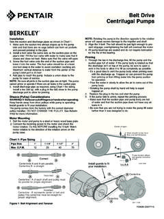
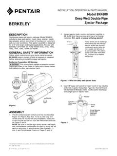
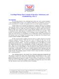
7 A PARTICULAR PURPOSE. THE FOREGOING LIMITED WARRANTIES SHALL NOT EXTEND BEYOND THE DURATION. PROVIDED HEREIN. Some states do not allow the exclusion or limitation of incidental or consequential damages or limitations on the duration of an implied warranty, so the above limitations or exclusions may not apply to You. This warranty gives You specific legal rights and You may also have other rights which vary from state to state. This Limited Warranty is effective June 1, 2011 and replaces all undated warranties and warranties dated before June 1, 2011. In the : BERKELEY, 293 Wright St., Delavan, WI 53115. In Canada: 269 Trillium Dr., Kitchener, Ontario N2G 4W5. Installation 4. Recommended pump suction Support discharge pipe as required and discharge connections Gate Valve Priming Plug Union Street Elbow Discharge to service Vent Plug Short length of straight pipe after reducer Important: All connections must be air tight Eccentric Support suction pipe Reducer as required Solid, level base Straight run, as short as possible but at least 6 times pipe diameter ("D"), sloping away from pump (pump inlet is highest point).
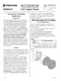
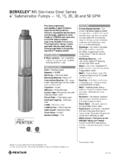
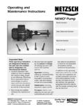
8 Pipe diameter Not recommended "D" As close pump suction and as possible discharge connections Figure 1. 4 x "D". On the discharge avoid: minimum Quick closing valves. Small pipe. Numerous fittings. Misalignment. Foot Sharp turns in piping run. Valve Long suction run Concentric Reducer Concentric Reducer causes high spots along the suction line resulting in air pockets. Valve Use of excess fittings means potential air leaks Unsupported Pipe high lift Pipe diameter "D". Elbow immediately too small in front of pump suction. Pipe submerged less than 4 x "D". will suck air Do not rotate discharge. Figure 2. 3343 1198. Installation 5. Piping - General Discharge Piping Support both suction and discharge piping independently Increase pipe size from pump tapping as shown in at a point near the pump to avoid putting a strain on the Table I. Figure 1 depicts a recommended run of pipe and pump housing. Start all piping AT THE PUMP.
9 Fittings for the discharge. Install tee with priming plug Increase pipe diameter at both the suction and discharge as close to pump as possible. Figure 2 notes conditions by one (1) standard pipe size (minimum) to obtain that should be avoided. Please read over carefully before desired performance and flow rate. Refer to Table I when making discharge connection. sizing pipe for your pumping system. Priming The Pump NOTICE Do not use pipe with smaller diameter on the A pump is primed when all air in the suction line suction side of pump. and pump volute has been evacuated and replaced Table I with water. Pipe Tapping Size On Pump Recommended Pipe Size To Prime: Suction Discharge Suction Discharge 1. Close valve in discharge line. 1-1/4 1 1-1/2 1-1/4 2. Remove priming plug from tee and fill pump and 1-1/2 1-1/4 2 1-1/2 suction line with water until water is flowing back out of tee. Suction Pipe 3. Replace priming plug.
10 Increase pipe size from pump tapping as shown in 4. Start pump and slowly open valve until desired water Table I. flow is achieved. Figure 1 depicts a recommended run of pipe and fittings NOTICE If no water is pumped after 5 minutes, turn for the suction side of a Centrifugal pump. Please refer to off pump, close valve, and repeat steps 1 thru 4. this illustration when choosing pipe and fittings for your suction connection. Risk of explosion and scalding. Never run pump against closed discharge. To do so can boil water NOTICE All connections must be air tight! inside pump, causing hazardous pressure buildup and Figure 2 depicts conditions that are NOT DESIRABLE possible explosion. on the suction side of a Centrifugal pump and may Risk of flooding. Can cause personal injury cause problems in flow rate and priming. Please look and/or property damage. Do not run the pump dry. This this illustration over carefully before choosing pipe and will damage mechanical seal and void warranty.