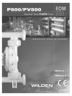
Transcription of P4/PX4 - Wilden Pumps
1 WIL-10310-E-07 Replaces WIL-10310-E-06 Simplify your processEngineering Operation &MaintenanceOriginal Series METAL PumpsP4/PX4 TABLE OF CONTENTSSECTION 1 CAUTIONS READ FIRST! ..1 SECTION 2 Wilden PUMP DESIGNATION SYSTEM ..2 SECTION 3 HOW IT WORKS PUMP & AIR DISTRIBUTION SYSTEM ..3 SECTION 4 DIMENSIONAL DRAWINGS ..4 SECTION 5 PERFORMANCEA. P4 Metal Performance CurvesRubber-Fitted ..6 TPE-Fitted ..6 PTFE-Fitted ..7 Full Stroke PTFE-Fitted ..7 Ultra-Flex -Fitted ..8 Suction Lift Curves ..9B. PX4 PerformanceOperating Principal .. 12 How to Use this EMS Curve .. 13 Performance CurvesRubber-Fitted .. 16 TPE-Fitted .. 17 PTFE-Fitted .. 18 Full Stroke PTFE-Fitted .. 19 Ultra-Flex -Fitted ..20 Suction Lift Curves ..21 SECTION 6 SUGGESTED INSTALLATION, OPERATION & TROUBLESHOOTING ..23 SECTION 7 DISASSEMBLY / REASSEMBLY.
2 26 SECTION 8 EXPLODED VIEW AND PARTS LISTINGP4 MetalFull Stroke Diaphragm-Fitted ..34 Reduced Stroke Diaphragm-Fitted ..361-Piece Center Section Full Stroke Diaphragm-Fitted ..381-Piece Center Section Reduced Stroke Diaphragm-Fitted ..40PX4 MetalFull Stroke Diaphragm-Fitted ..42 Reduced Stroke Diaphragm-Fitted ..44 SECTION 9 ELASTOMER OPTIONS ..46 WIL-10310-E-07 1 Wilden PUMP & ENGINEERING, LLC CAUTION: Do not apply compressed air to the exhaust port pump will not function. CAUTION: Do not, under any circumstance, loosen the set screw located at the adjust dial of the Pro-Flo X pump. If the set screw is loose when the pump is pressurized, it could eject and cause injury to anyone in the area. CAUTION: Do not over-lubricate air supply excess lubrication will reduce pump performance.
3 Pump is pre-lubed. TEMPERATURE LIMITS: Neoprene C to C 0 F to 200 F Buna-N C to C 10 F to 180 F EPDM C to C 60 F to 280 F Viton 40 C to C 40 F to 350 F Sanifl ex C to C 20 F to 220 F Polytetrafl uoroethylene (PTFE) C to C 40 F to 220 F Polyurethane C to C 10 F to 150 F Tetra-Flex PTFE w/Neoprene Backed C to C 40 F to 225 F Tetra-Flex PTFE w/EPDM Backed -10 C to 137 C 14 F to 280 F NOTE: Not all materials are available for all models. Refer to Section 2 for material options for your pump. CAUTION: When choosing pump materials, be sure to check the temperature limits for all wetted components. Example: Viton has a maximum limit of C (350 F) but polypropylene has a maximum limit of only 79 C (175 F).
4 CAUTION: Maximum temperature limits are based upon mechanical stress only. Certain chemicals will signifi cantly reduce maximum safe operating temperatures. Consult Chemical Resistance Guide (E4) for chemical compatibility and temperature limits. WARNING: Prevention of static sparking If static sparking occurs, fi re or explosion could result. Pump, valves, and containers must be grounded to a proper grounding point when handling fl ammable fl uids and whenever discharge of static electricity is a hazard. CAUTION: Do not exceed bar (125 psig) air supply pressure. CAUTION: The process fl uid and cleaning fl uids must be chemically compatible with all wetted pump components. Consult Chemical Resistance Guide (E4). CAUTION: Do not exceed 82 C (180 F) air inlet temperature for Pro-Flo X models.
5 CAUTION: Pumps should be thoroughly fl ushed before installing into process lines. FDA and USDA approved Pumps should be cleaned and/or sanitized before being used. CAUTION: Always wear safety glasses when operating pump. If diaphragm rupture occurs, material being pumped may be forced out air exhaust. CAUTION: Before any maintenance or repair is attempted, the compressed air line to the pump should be disconnected and all air pressure allowed to bleed from pump. Disconnect all intake, discharge and air lines. Drain the pump by turning it upside down and allowing any fl uid to fl ow into a suitable container. CAUTION: Blow out air line for 10 to 20 seconds before attaching to pump to make sure all pipeline debris is clear. Use an in-line air fi lter. A 5 (micron) air fi lter is recommended.
6 NOTE: When installing PTFE diaphragms, it is important to tighten outer pistons simultaneously (turning in opposite directions) to ensure tight fi t. (See torque specifi cations in Section 7.) NOTE: Cast Iron PTFE-fi tted Pumps come standard from the factory with expanded PTFE gaskets installed in the diaphragm bead of the liquid chamber. PTFE gaskets cannot be re-used. Consult PS-TG for installation instructions during reassembly. NOTE: Before starting disassembly, mark a line from each liquid chamber to its corresponding air chamber. This line will assist in proper alignment during reassembly. CAUTION: Pro-Flo Pumps cannot be used in submersible applications. Pro-Flo X is available in both submersible and non-submersible options. Do not use non-submersible Pro-Flo X models in submersible applications.
7 Turbo-Flo Pumps can also be used in submersible applications. CAUTION: Tighten all hardware prior to 1 CAUTIONS READ FIRST! Wilden PUMP & ENGINEERING, LLC 2 WIL-10310-E-07 NOTE: MOST EL ASTOMERIC MATERIALS USE COLORED DOTS FOR : Not all models are available with all material is a registered trademark of DuPont Dow is a registered trademark of CODES014 BSP023 Wing nuts030 Screen based036 Screen based, BSP044 Stallion, balls & seats ONLY047 Stallion externals, balls and seats067 Saniflo FDA, Wil-Gard 220V070 Saniflo FDA075 Saniflo FDA, Stallion balls and seats079 Tri-clamp fittings, wing nuts080 Tri-clamp fittings ONLY100 Wil-Gard 110V102 Wil-Gard sensor wires ONLY103 Wil-Gard 220V108 BSP, Wil-Gard 220V118 Stallion balls and seats ONLY, BSP120 Saniflo FDA, Wil-Gard 110V330 Wing nuts BSPS ection 2 Wilden PUMP DESIGNATION SYSTEMP4/PX4 METAL38 mm (1-1/2") PumpMaximum Flow Rate.
8 348 lpm (92 gpm)LEGENDPX4 / X X XX X / XXX / XX / X XX /XXXXO-RINGSMODELVALVE SEATVALVE BALLSDIAPHRAGMSAIR VALVECENTER BLOCKAIR CHAMBERSWETTED PARTS & OUTER PISTONSPECIALTYCODE(if applicable)MATERIAL CODESMODELP4 = PRO-FLO PX4 = PRO-FLO X WETTED PARTS & OUTER PISTONAA = ALUMINUM / ALUMINUMSS = STAINLESS STEEL / STAINLESS STEELWW = CAST IRON / CAST IRONWM = CAST IRON / MILD STEELAIR CHAMBERS/CENTER SECTIONA = ALUMINUML = ACE TAL (P4 only)N = NICKEL-PL ATEDS = STAINLESS STEELV = HAL AR COATED (P4 only)CENTER SECTION/BLOCKA = ALUMINUM (PX4 only)L = ACE TAL (P4 only)N = NICKEL-PL ATED (PX4 only)P = POLYPROPYLENE (P4 only)S = STAINLESS STEEL(PX4 only)AIR VALVEA = ALUMINUM (PX4 only)L = ACE TAL (P4 only)N = NICKEL-PL ATED (PX4 only)P = POLYPROPYLENE S = STAINLESS STEEL(PX4 only)DIAPHRAGMSXBS = CONDUCTIVE BUNA-N (Two Red Dots)BNS = BUNA-N (Red Dot)FSS = SANIFLEXTM [Hytrel (Cream)]EPS = EPDM (Blue Dot)NES = NEOPRENE (Green Dot)PUS = POLYURETHANE (Clear)TEU = PTFE W/EPDM BACK-UP (White)TNU = PTFE W/NEOPRENE BACK-UP (White)TSU = PTFE W/SANIFLEXTM BACK-UP (White)BNU = BUNA-N, ULTRA-FLEXTM (Red Dot)EPU = EPDM, ULTRA-FLEXTM (Blue Dot)NEU = NEOPRENE, ULTRA-FLEXTM (Green Dot)
9 VTU = VITON , ULTRA-FLEXTM (White Dot)VTS = VITON (White Dot)WFS = WIL-FLEXTM [Santoprene (Orange Dot)]TSS = FULL STROKE PTFE W/SANIFLEX BACK-UPTWS = FULL STROKE PTFEW/WIL-FLEX BACK-UPVALVE BALLBN = BUNA-N (Red Dot)FS = SANIFLEX [Hytrel (Cream)]EP = EPDM (Blue Dot)NE = NEOPRENE (Green Dot)PU = POLYURETHANE (Clear)TF = PTFE (White)V T = VITON (Silver or White Dot)WF = WIL-FLE X [Santoprene (Orange Dot)]VALVE SEATA = ALUMINUMBN = BUNA-N (Red Dot)FS = SANIFLEX [Hytrel (Cream)]H = ALLOY CM = MILD STEELEP = EPDM (Blue Dot)NE = NEOPRENE (Green Dot)PU = POLYURETHANE (Clear)S = STAINLESS STEELV T = VITON (Silver or White Dot)WF = WIL-FLE X [Santoprene (Orange Dot)]VALVE SEAT O-RINGTF = PTFEThe Wilden diaphragm pump is an air-operated, positive displacement, self-priming pump.
10 These drawings show fl ow pattern through the pump upon its initial stroke. It is assumed the pump has no fl uid in it prior to its initial 1 The air valve directs pressurized air to the back side of diaphragm A. The compressed air is applied directly to the liquid column separated by elastomeric diaphragms. The diaphragm acts as a separation membrane between the compressed air and liquid, balancing the load and removing mechanical stress from the diaphragm. The compressed air moves the diaphragm away from the center of the pump. The opposite diaphragm is pulled in by the shaft connected to the pressurized diaphragm. Diaphragm B is on its suction stroke; air behind the diaphragm has been forced out to atmosphere through the exhaust port of the pump.