Transcription of P470 Electronic Pressure Control with DIsplay Product ...
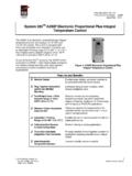
1 P470 Electronic Pressure Control with DIsplay Product / technical Bulletin1 Refer to the QuickLIT website for the most up-to-date version of this P470 Electronic Pressure Control with DIsplay is a single-stage, On/Off, Electronic Pressure Control with a Single-Pole, Double-Throw (SPDT) output relay. The Control may be field set to operate in one of three Pressure ranges (0 to 100 psi, 0 to 500 psi, or 50 to 750 psi), as either an open-high or open-low P470 Control features a large LCD that displays the sensed Pressure and other system-status indicators, as well as the adjustable setpoints in the programming mode. The P470 Control has a lockable, three-button touchpad for adjusting setpoints, and a front-panel LED that indicates the output relay P470 Control uses a P499 Electronic Pressure Transducer in conjunction with a WHA-PDK3 Wiring Harness to sense system Pressure . This arrangement virtually eliminates the chance of a refrigerant leak because there are no capillaries or bellows to break or 1: P470 Pressure Control with Transducer and Wiring Harness ( Control , transducer, and harness must be purchased separately.)
2 Table 1: Features and BenefitsFeaturesBenefitsEasy to Read Liquid Crystal DIsplay (LCD)Clearly displays the sensed Pressure (and other Control information), and in many situations Pressure may be monitored without applying gauges to the controlled equipmentThree Field-Selectable Pressure Ranges between 0 750 psi Provides the flexibility to cover most HVACR Pressure applications with three field-selectable Pressure ranges; 0 100 psi with 5 psi minimum differential, and 0 500 psi or 50 750 psi with 20 psi minimum differential24 VAC, and 120 or 208/240 VAC ModelsIncreases application options, with two controls that cover most common voltagesLockable, 3-Button, Front-Panel TouchpadDeters tampering and over adjustment of Control settings by unauthorized personnelBuilt-in, Adjustable, Anti-Short Cycle Time-DelayReduces compressor short cycling and nuisance lockouts, which can extend compressor lifeUses an Economical and Versatile Transducer and Wiring HarnessEliminates many of the constraints of capillary Control applications and allows up to a 100 ft ( m) cable between Control and transducerP470 Electronic Pressure Control with DisplayProduct/ technical BulletinCode No.
3 LIT-125528 Part No. 24-7664-2004, Rev. BIssued April 28, 2014 Supersedes January 26, 2012P470 Electronic Pressure Control with DIsplay Product / technical Bulletin2 Application Application OptionsThe P470 Electronic Pressure Control with DIsplay is designed for On/Off Control (direct or pilot duty) of refrigeration and HVAC loads based on system P470 Control s overall setpoint range is 0 to 750 psi. The available operating ranges are: 0 to 100 psi, 0 to 500 psi, and 50 to 750 psi, depending on which P499 transducer is wired to the Control . See Table 2 for more :Each of the P470 Control s three field-selectable, operating Pressure ranges require a specific P499 transducer to operate properly. See Table 2 for more P499 transducer may be used with any fluid or vapor that is compatible with 17-4PH stainless steel. This includes all non-corrosive refrigerants and P470 Control may replace a variety of electromechanical Pressure controls, and provides a clear LCD DIsplay of the controlled equipment Pressure .
4 The transducer may be mounted up to 100 ft ( m) away from the Control using three-wire shielded cable, providing greater installation versatility, and eliminating many of the constraints of capillary tubes found on electro-mechanical Pressure may use a maximum of four P470 controls wired to a single P499 transducer. For example, high- Pressure Control and condenser fan cycling can use a common transducer in conjunction with two P470 Controls to Control high-side Pressure . The P470 Controls may be connected to a single transducer on the suction manifold to stage four compressors on a refrigeration rack. See Figure OverviewThe P470 Control uses a P499 Electronic Pressure Transducer to sense Pressure . The Control s operating Pressure range depends on the transducer model selected and the position of the Pressure range jumpers. See Positioning the Jumpers and Table P499 transducer is mounted to a Pressure tap point on the refrigerant system.
5 The transducer generates a to VDC ratiometric signal that the P470 Pressure Control converts to a psi value. Refer to the P499 Electronic Pressure Transducer Product / technical bulletin (LIT-12011190).The sensed psi value is refreshed every two seconds and displayed on the Liquid Crystal DIsplay (LCD), along with other Control status information, during normal operation. See Figure the Pressure at the transducer reaches the cut-in setpoint, the output relay is energized, the front-panel LED lights, the Normally Open ( ) contacts close, and the Normally Closed ( ) contacts open. When the cutout setpoint is reached, the output relay is de-energized, the LED goes off, and the contacts return to their normal :Use this P470 Electronic Pressure Control only as an operating Control . Where failure or malfunction of the P470 Control could lead to personal injury or property damage to the controlled equipment or other property, additional precautions must be designed into the Control system.
6 Incorporate and maintain other devices, such as supervisory or alarm systems or safety or limit controls, intended to warn of or protect against failure or malfunction of the P470 :Utiliser ce P470 Electronic Pressure Control uniquement en tant que dispositif de contr le de fonctionnement. Lorsqu'une d faillance ou un dysfonctionnement du P470 Control risque de provoquer des blessures ou d'endommager l' qui-pement contr l ou un autre quipement, la concep-tion du syst me de contr le doit int grer des dispositifs de protection suppl mentaires. Veiller dans ce cas int grer de fa on permanente d'autres dispositifs, tels que des syst mes de super-vision ou d'alarme, ou des dispositifs de s curit ou de limitation, ayant une fonction d'avertissement ou de protection en cas de d faillance ou de dysfonc-tionnement du P470 Electronic Pressure Control with DIsplay Product / technical bulletin 3 DimensionsLiquid Crystal DisplayThe P470 Control has an LCD that displays the sensed Pressure during normal operation.
7 See Figure LCD also displays whether the Control is operating with the primary or secondary setpoints (S1 or S2 is displayed in upper right corner), and indicates if the Control is operating as an Open-high ( ) or Open-low ( ) Control . (See Figure 3.) The LCD also indicates if the Control is in Anti-Short Cycle Delay. See Anti-Short Cycle adjusting the Control , the LCD displays the adjustable setpoints and their values. See Table 3 and the Adjustments section for information on DIsplay codes and changing the settings. After 30 seconds of inactivity at the touchpad, the Control and DIsplay return to normal operation. See Figure Pressure Control SettingsThe P470 Control allows the user to establish a variety of Control settings by positioning jumpers inside the Control and using the three-button touchpad to change setpoint values. For specific instructions, see the Positioning the Jumpers and Changing Setpoint Values and Anti-short Cycle Delay Time-Interval Adjustable SetpointsCut-InCut-In establishes the Pressure value (in psi) at which the output relay is energized, which closes the contacts, opens the contacts, and the LED is 2: P470 Electronic Pressure Control Dimensions, inches (mm)Figure 3: P470 Control Operating DisplayPSII ndicates if the Control is operating with either the Primary () or Secondary () setpoints.
8 (Donly the indicator for the active setpoints in use is visible in black. )S1S2uring normal operation is shown here in gray to illustrate its position on the LCD. S2 Indicates Pressure (in psi) sensed at the if the Control is operating as an open-low or open-high Pressure Control .(During normal operation only one of the two icons is visible in black. The open-high icon is shownhere in gray to illustrate its position on the LCD.)FIG:P470_dsplyP470 Electronic Pressure Control with DIsplay Product / technical Bulletin4 CutoutCutout establishes the Pressure value (in psi) at which the output relay is de-energized, returning the contacts to their normal positions, and the LED is the cut-in and cutout values are established, the P470 Control automatically determines the Control operation and displays either an Open-high ( ) or Open-low ( ) icon in the lower right of the LCD during normal operation. See Figure cut-in (ci1) and cutout (co1) values establish the primary setpoints (S1).
9 A secondary set (S2) of cut-in (ci2) and cutout (co2) values may be also be set. The S2 setpoints are enabled by a user-supplied Single-Pole, Single-Throw (SPST) switching device such as a Control -clock or temperature Control . See Secondary Cut-in and Cutout Setpoints for Cycle DelayAnti-Short Cycle Delay establishes the minimum time that the controlled equipment remains off before starting again. The anti-short cycle delay activates when the output relay de-energizes. The delay does not allow the output relay to re-energize until the user-set delay time has elapsed. When the delay is activated, the LCD flashes (alternately) the sensed Pressure value and A x, where x is the number of minutes of remaining delay time. The anti-short cycle delay may be programmed for 0 to 9 minutes in 1-minute :A 0 indicates that the Control is in the final minute of the delay :Any power interruption to the Control also activates the anti-short cycle Cut-in and Cutout SetpointsSecondary Cut-in and Cutout Setpoints establish a second set of cut-in and cutout values, which are enabled when a circuit is closed between the binary input terminals (SP2 and COM) on the upper terminal block (TB3).
10 When the secondary setpoints are enabled, S2 is displayed instead of S1 in the upper right corner of the LCD. See Figure Established by Jumper PositionTwo of the P470 Control settings are established by positioning jumpers inside the Control . These parameters are explained in the following section. For instructions on how to position the jumpers, see Positioning the Jumpers in the Adjustments Range JumperPressure Range Jumper positions establish the operational Pressure range of the P470 Control . Each of the three Pressure ranges requires a specific P499 transducer with a matching range. See Table 2 for transducer model and Pressure range Pressure range jumpers may be positioned to operate the Control in a 0 100, 0 500, or 50 750 psi range. See Positioning the Jumpers and Table Lock JumperTouchpad Lock Jumper position establishes if the front panel may be used to adjust the Control or not. Locking out the touchpad helps deter tampering or accidental changes to the established :The P470 Control settings are non-volatile and remain in the Control s memory during power :When mounting the P470 Control to rigid conduit, attach the hub to the conduit before securing the hub to the Control P470 Control has a NEMA 1 plastic enclosure with four key-slot mounting holes on the back for surface mounting.
