Transcription of PACIFIC STATES CAST IRON PIPE COMPANY
1 PACIFIC STATESCAST IRON PIPECOMPANYA division of mcwane , Offi ces and Plant801-373-6910 Telephone801-377-0338 Facsimile Mailing Address: Street Address: Box 1219 1401 East 2000 South Provo, Utah 84603 Provo, Utah local contact information please visit our website. TYTON and TYTON JOINT are registered trademarks of United STATES Pipe and Foundry COMPANY , Inc. FASTITE is a registered trademark of American Cast Iron Pipe COMPANY . VITON is a registered trademark of Dupont Dow Elastomers, LLC. THRUST-LOCK is a registered trademark of Pacifi c STATES Cast Iron Pipe COMPANY , Inc. All other trademarks belong to their respective c STATES Cast Iron Pipe Co. 47 Mechanical with Tyton JointDrawings and DimensionsSizeOD with TYTON JOINT Pipe Assembly Step 1. Thoroughly clean out the bell with special attention to the gasket recess. Remove any foreign material or excess paint. Clean the spigot or beveled plain end and remove any sharp edges with a standard fi le.
2 Step 2. After making sure that the correct gasket is being used, insert it into the recess in the bell with the small end of the gasket facing the bell face. Step 3. Place the wedge type restraining devise on the plain end with the lip extension toward the plain end. Step 4. Apply lubricant to the inside surface only of the gasket, making sure that the entire surface is coated. Apply a generous coating of lubricant to the beveled portion of the plain end. Guide the plain end into the bell and, while maintaining straight alignment, push the plain end into the bell socket. Step 5. Insert and start the nuts on the T-head bolts. Step 6. Defl ect the joint to the desired alignment. When assembly is complete, the bell face should be aligned between the two white depth rings. Step 7. Tighten the T-head bolts to fi nger tight. Step 8. Tighten the wedge type restraining device to the manufactures recommended Pacifi c STATES Cast Iron Pipe DEFLECTION FOR FULL LENGTH PIPEMECHANICAL with TYTON JOINT PIPEM aximum Allowable Joint Defl ectionPipe Joint Defl ection in DegreesX Defl ection in Inches 18 ft.
3 LengthApproximate Radius in ft. of Curve Produced by Succession of Joints 18 ft. Length65 1920585 19205105 19205125 19205145 19205165 19205185 19205205 19205245 19205 Pacifi c STATES Cast Iron Pipe Co. 49 FIELD CUTTING MECHANICAL WITH TYTON JOINT PIPEWhen it is necessary to fi eld cut ductile iron pipe, the installer should select a piece of pipe that has been marked for fi eld cutting. All ductile iron pipe has a slight taper due to the manufacturing process. If the pipe is not marked for fi eld cutting then the diameter of the pipe should be checked prior to cutting. This can be done with an OD tape or by using an MJ follower to check the diameter of the pipe. No pipe should be cut within 24 inches of the bell Pipe Diameter Pipe Diameter Pipe Circumference Pipe Circumference Table Based on ANSI/AWWA C151 Guidelines for Push-On Pacifi c STATES Cast Iron Pipe CLASS SUBMITTAL MECHANICAL WITH TYTON JOINT Selection Table for Laying ConditionsThis table shows pressure class of pipe necessary for the rated water working pressures and maximum depth of cover.
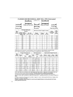
4 The thicknesses in this table are equal to or in excess of those required to withstand the rated working pressures plus a surge allowance of 100 psi. Ductile iron pipe for working pressures higher than 350 psi is ConditionsType 1 TrenchType 2 TrenchType 3 TrenchType 4 TrenchType 5 TrenchMaximum depth of cover 11** 10** 11** 11** 10** 8** 15192837 An allowance for a single H-20 truck with impact factor is included for all depths of cover. Calculated maximum depth of cover exceeds 100 ft ( m).**Minimum allowable depth of cover is 3 ft ( m). For pipe 14 in. (350 mm) and larger, consideration should be given to the use of laying conditions other than Type c STATES Cast Iron Pipe Co. 51 PRESSURE CLASS SUBMITTAL MECHANICAL WITH TYTON JOINT Thickness, Dimensions and Weights of by Size for Each Pressure Class * of BarrelPer Ft. Lb. Wt. PerLgth. WtPer Ft. ** * Tolerances of OD of spigot end; 3-12 in in.
5 , 14-24 in. + in., in.** Average lengths only. Variances may occur as a result of foundry processes or installation. Including bell; calculated weight of pipe rounded off to the nearest 5 lb. Including bell; average weight per foot, based on calculated weight of pipe before Pacifi c STATES Cast Iron Pipe CLASS SUBMITTAL MECHANICAL WITH TYTON JOINT Selection Table for Laying ConditionsThis table shows thickness class of pipe necessary for the rated water working pressures and maximum depth of cover. The thicknesses in this table are equal to or in excess of those required to withstand the rated working pressures plus a surge allowance of 100 psi. Ductile iron pipe for working pressures higher than 350 psi is ConditionMaximum Depth of Cover, Feet Type 1 TrenchType 2 TrenchType 3 TrenchType 4 TrenchType * *100* *100*100*100* *100*100*100*100* *100*100*100*100* *100*100*100*100* *100* *100*100* *100*100*100* *100*100*100*100* * *100* *100*100* * *100* An allowance for single H-20 truck with impact factor is included for all depths of cover.
6 *Calculated maximum depth of cover exceeds 100 ft. Calculated maximum depth of cover is 3ft ( m). For pipe 14 in. (350 mm) and larger, consideration should be given to the use of laying conditions other than Type c STATES Cast Iron Pipe Co. 53 THICKNESS CLASS SUBMITTAL MECHANICAL WITH TYTON JOINT Selection Table for Laying ConditionsPipe ConditionsMaximum Depth of Cover, Feet Type 1 TrenchType 2 TrenchType 3 TrenchType 4 TrenchType * An allowance for single H-20 truck with impact factor is included for all depths of cover.*Calculated maximum depth of cover exceeds 100 ft. Calculated maximum depth of cover is 3ft ( m). For pipe 14 in. (350 mm) and larger, consideration should be given to the use of laying conditions other than Type Pacifi c STATES Cast Iron Pipe CLASS SUBMITTAL MECHANICAL WITH TYTON JOINT PIPET hickness, Dimensions and Weights of Pipe by Size for Each ThicknessPipe Size * of BarrelPer Ft. Lb. Wt. PerLgth.
7 Ft. ** Including bell; calculated weight of pipe rounded off to the nearest 5lb. Including bell; average weight per foot, based on calculated weight of pipe before rounding.*Tolerances of OD of spigot end; 3-12 in. in., 14-24 in. + in., in.**Average lengths only. Variances may occur as a result of foundry processes or installation. Pacifi c STATES Cast Iron Pipe Co. 55 THICKNESS CLASS SUBMITTAL MECHANICAL WITH TYTON JOINT PIPET hickness, Dimensions and Weights of Pipe by Size for Each ThicknessPage Size * of BarrelPer Ft. Lb. Wt. PerLgth. ft. Lb. Laying** Including bell; calculated weight of pipe rounded off to the nearest 5lb. Including bell; average weight per foot, based on calculated weight of pipe before rounding.*Tolerances of OD of spigot end; 3-12 in. in., 14-24 in.+ in., in., 30-36 in. + in., in.**Average lengths only. Variances may occur as a result of foundry processes or Pacifi c STATES Cast Iron Pipe CONDITIONS FOR DUCTILE IRON PIPEType 1*Flat-bottom trench.
8 Loose backfi 2 Flat-bottom trench. Backfi ll lightly consolidated to centerline of 3 Pipe bedded in 4 in. (100 mm) minimum of loose soil.++Backfi ll lightly consolidated to top of 4 Pipe bedded in sand, gravel, or crushed stone to depth of 1/8 pipe diameter, 4 in. (100 mm) mini-mum. Backfi ll compacted to top of pipe. (Approxi-mately 80 percent Standard Proctor, AASHTO T-99.)Type 5 Pipe bedded in compacted granular material to centerline of pipe. Compacted granular or select material++ to top of pipe. (Approximately 90 percent Standard Proctor, AASHTO T-99.)*For 14 in. (355-mm) and larger pipe, consideration should be given to the use of laying conditions other than Type 1. Flat-bottom is defi ned as undisturbed earth.++ Loose soil or select material is defi ned as native soil excavated from the trench, free of rocks, foreign materials, and frozen c STATES Cast Iron Pipe Co. 57 SHORT FORM SPECIFICATION For Mechanical with Tyton Joint PipeSCOPEThis specifi cation covers the general requirements for Pacifi c STATES Mechanical with Tyton Joint ductile iron iron pipe 6 through 24 shall be manufactured in accordance with ANSI/AWWA C151 under method of design outlined in ANSI/AWWA C150 joints shall be Mechanical with Tyton Joint 6 through 24 and shall meet the requirements of ANSI/AWWA C111 CoatingExternal pipe coating shall be an asphaltic coating in accordance with ANSI/AWWA C151 for pipe and ANSI/AWWA C110 for fi Pipe LiningThe pipe shall be cement-mortar lined in accordance with ANSI/AWWA C104 RATINGSFor pressures higher than 350 psi contact your local sales for ductile iron pressure pipe shall be produced in accordance with ANSI/AWWA C110


![Untitled-1 [pe.mcwane.com]](/cache/preview/0/6/a/a/7/a/e/3/thumb-06aa7ae3820fc1a116eff00b799cf8bf.jpg)