Transcription of PACKAGE INFORMATION 1. PACKAGE CLASSIFICATIONS
1 This version:Apr. 2001 Previous version: Jun. 1997 PACKAGE INFORMATION1. PACKAGE CLASSIFICATIONSThis document is Chapter 1 of the PACKAGE INFORMATION document consisting of 8 chapters INFORMATION1. PACKAGE CLASSIFICATIONS11. PACKAGE TrendsIn recent years, marked advances have been made in the electronics field. One such advance has been theprogression from vacuum tubes to transistors and finally, to ICs. ICs themselves have been more highlyintegrated into LSIs, VLSIs, and now, increased functions and pin counts, IC packages have had to change significantly in the last few years inorder to keep-up with the advancement in semiconductor required for conventional IC packages are as follows.
2 1)To protect IC chips from the external environment2)To facilitate the packaging and handling of IC chips3)To dissipate heat generated by IC chips4)To protect the electrical characteristics of the ICStandard dual-in-line packages (DIP), which fulfill these basic requirements, have enjoyed wide usage in theelectronics industry for a number of increasing integration and higher speed ICs, and with the miniaturization of electronic equipment, newerpackages have been requested by the industry which incorporate the functions listed below:1)Multi-pin I/O2)Ultra-miniature packages3)Packages suited to high density ICs4)Improved heat resistance for use with reflow soldering techniques5)High throughput speed6)Improved heat dissipation7)Lower cost per pinIn response to these requests, OKI has developed a diversified family of packages to meet the myriad requirementsof today s burgeoning electronics INFORMATION1.
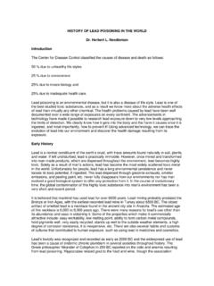
3 PACKAGE CLASSIFICATIONS2 PGASKINNY DIPZIPSHRINK-DIPDIPSOPSOJQFJQFPTQFP/LQFP TCPBGA/LGACSPSSOPTSOPS maller sizeSURFACE MOUNTING TYPEH igher Pin CountFigure Packaging TrendPACKAGE INFORMATION1. PACKAGE CLASSIFICATIONS310080604020199520002005 Through-hole mounting type PACKAGE (DIP, ZIP, SIP, PGA, etc.)Surface mounting type PACKAGE (SOP, QFP, SOJ, QFJ, BGA)Tape carrier (TCP)COB, TCP, rate (%)Figure IC PACKAGE Demand Trend ForecastPACKAGE INFORMATION1. PACKAGE Classification[Classification by the mounting method]1)Through-hole mount packagesThrough-hole packages have a structure in which the lead pins are inserted and soldered into holes ( to in diameter) drilled through the printed circuit (PC) board, and find wide applications in electronicequipment where board space is not at a premium or where costs are a , and PGAs are typical packages in this group.
4 ZIPs, skinny DIPs, and shrink DIPs are high-pin-density IC packages which can be used in these )Surface mount packagesSurface mount packages have a flat structure in which the lead pins are soldered directly to the solderedpattern (called the mount pad) provided on the PC board, and are used in high-pin-density IC packagesituations because devices can be mounted on both sides of the PC board. QFPs and QFJs (PLCC) aretypical packages in this )Custom packagesMemory modules are packages which have several memory ICs mounted on a PC board, Tape carrierpackages (TCP) using Tape Automated Bonding (TAB) techniques, Chip On Board (COB) packages, or ICcard packages.
5 TCP and COB packages are custom designs conforming to the customer s specifications.[Classification by PACKAGE materials]Packages are broadly classified into ceramic and plastic packages. PACKAGE materials can be selectedaccording to their application or operating packages are known for their high reliability, but plastic packages are becoming more popular due totheir low cost (when compared to ceramic packages). Reliability has improved considerably in the last fewyears making plastic a very attractive alternative to INFORMATION1. PACKAGE CLASSIFICATIONS5IC packages are classified as indicated below according to shape, material, and mounting PACKAGE ClassificationQFPTQFP/LQFPSOPSSOPTSOPSOJ QFJ (PLCC)BGA/FBGAS kinny DIPS hrink DIPZIPQFPPGADIPTCP (TAB)COBSIMMDIMMDIPQuad Lead RowsStandardMiniatureFlatMatrixFlatSurfa ceMountingTypePackageTypeCeramic&CER-DIP S ocketTypeMemoryModulePlasticCustomTypeCh ipCarrierSingle LeadRowsDual LeadRowsMatrixDual LeadRowsThrough-holeMountingTypeThrough- holeMountingTypeSurfaceMountingTypeQuad Lead RowsQuad Lead RowsStandardFLGAW-CSPCOTDual Lead RowsDual Lead RowsPACKAGE INFORMATION1.
6 PACKAGE Type and Characteristics1)Through-hole mounting type packagePackage SymbolTypePackage TypesOldNewPin CountStandardRSRA8, 14, 16, 18, 20, 22,24, 28, 32, 36, 40, 42,48 SkinnyRSRC20, 22 DlPShrinkSSRB30, 42, 64 Through-hole Mounting TypePlasticZIPZSRD20, 24, 28, 40 PACKAGE INFORMATION1. PACKAGE CLASSIFICATIONS7 PACKAGE NameCharacteristicsDual In-line PackageStandard DIP packages are most widely used. The lead pitch is mm(100 mil), and the spacing between terminal rows is 300, 400, or 600 Dual In-line PackageSkinny DIP packages are standard DIPs with spacing between terminalrows of mm (300 mil) and with 20 or more Dual In-line PackageShrink DIP packages are standard DIPs with a lead pitch reduced to (70 mil).
7 They are smaller in external size than standard DIPs andsuited to compact electronic equipment using high-pin-density IC In-line PackageZIP packages are featured by the leads which are drawn out from eachpackage body into a single row to allow vertical mounting with a lead pitch mm (50 mil). The leads of each PACKAGE are Zigzag folded, within thepackage surface thickness, into two rows. The Zigzag folding increasesthe lead pitch in each row to mm (100 mil). PACKAGE INFORMATION1. PACKAGE CLASSIFICATIONS8 PACKAGE SymbolTypePackage TypesOldNewPin CountStandard DIPASAA14, 16, 18, 20, 22, 24,28, 40, 42, 48 CER-DIPASAB8, 14, 16, 18, 22, 24,28, 32, 40, 42 Through-hole Mounting TypeCeramicPGAASBA73*2, 88, 133*2, 177*2,209*2, 257*2, 301*2,240, 365*2, 400*1 Under development*2 The PGA pin count includes a pin for preventing incorrect insertion.
8 *1 PACKAGE INFORMATION1. PACKAGE CLASSIFICATIONS9 PACKAGE NameCharacteristicsDual In-line PackageDIP packages are hermetic ceramic PACKAGE . The lead pitch is mm(100 mil) and the PACKAGE body is made of ceramics. Metal or glass maybe used as a sealing In-line PACKAGE (Glass Sealed)Dual In-line packages are called CER-DIP lead pitch is mm (100 mil), and the PACKAGE body is molded withpowder ceramics. The sealing material is Grid ArrayPGA packages are featured by the leads which are drawn out vertically fromeach PACKAGE body and arranged on the specified grid. The PACKAGE bodyis made of ceramics, and the standard lead pitch is mm (100 mil).PGA packages are suited to multipin INFORMATION1. PACKAGE CLASSIFICATIONS102)Surface mounting type packagePackage SymbolTypePackage TypesOldNewPin CountMSMA8, 16 SOPGSMA24, 28, 32, 40, 44 MSMB20 GSMB30, 32, 60, 64, 70 SSOPGS-BMB60 TSOP(1)32, 40*1 TSOP(2)TSTA26/20, 26/24, 28/24, 28, 32,44/40, 44, 48, 50/44, 50,54, 66*1, 70/64, 70, 86*1 GSGA44, 56, 64, 80, 100, 128,160, 208, 240, 272, 304GS-2GA44, 56 QFPGS-BGA64, 80, 100 High HeatDissipation QFP*2GS-CGA208 TQFPTSTB44, 48, 64, 80, 100, 120 LQFPGSTC144, 176, 208 SOJJS (SJ)JA26/20, 26/24, 28/24, 28,32, 36, 40, 42, 50 QFJ(PLCC)JSJB18, 20, 22, 28, 32, 44, 68,84 BGA/FBGALSLA48, 84, 104, 144, 176, 224,256, 352, 420, 560 FLGA LB49, 56, 84 Surface Mounting TypePlasticWafer LevelCSP (W-CSP)
9 HA, HBCustom design*1 Under development*2 Built-in Heat SpreaderPACKAGE INFORMATION1. PACKAGE CLASSIFICATIONS11 PACKAGE NameCharacteristicsSmall Out-lineL- leaded PackageSOP packages are characterized by gull-wing type leads which are drawnout from each PACKAGE body in two directions, and can be mounted standard lead pitch is mm (50 mil).Shrink Small Out-lineL- leaded PackageSOP packages with a lead pitch of less than mm (50 mil) are Small Out-lineL- leaded PackageTSOP packages are ultra thin SOPs with a PACKAGE L- leaded mountingheight of less than mm, and are suited to ultra-thin electronicequipment such as smart Flat L- leaded PackageQFP packages are characterized by gull-wing type leads which are drawnout from each PACKAGE body in four directions, and can be mounted are various QFPs available because the lead pitch is variable and thedimensions of the PACKAGE body Flat L-LeadedPackage with Heat SinkQFP packages with a heat sink.
10 (for high power device)Quad Flat L-LeadedPackage with Heat SpreaderQFP packages with built-in heat spreader. (for high power device)Thin Quad FlatL- leaded PackageThin QFP packages have the PACKAGE body heights (mold thickness) mm and of Profile Quad FlatL- leaded PackageLQFP packages have the PACKAGE body height (mold thickness) of Out-lineJ- leaded PackageSOJ packages are characterized by J-shaped leads which are drawn outfrom each PACKAGE body in two directions, and can be mounted standard lead pitch is mm (50 mil).Quad Flat J- leaded PackageQFJ packages are characterized by J-shaped leads which are drawn outfrom each PACKAGE body in four directions, and can be mounted standard lead pitch is mm (50 mil).