Transcription of Page 1 MODEL 345 ROOF-MOUNT POWERED …
1 Page 1 MODEL 345 WARNING TO REDUCE THE RISK OF FIRE, ELECTRIC SHOCK, OR INJURY TO PERSONS, OBSERVE THE FOLLOWING:1. Use this unit only in the manner intended by the manufacturer. If you have any questions, contact the manufacturer at the address or telephone number listed in the Before servicing or cleaning unit, switch power off at service panel and lock the service disconnecting means to prevent power from being switched on accidentally. When the service disconnecting means cannot be locked, securely fasten a prominent warning device, such as a tag, to the service Installation work and electrical wiring must be done by a qualified person(s) in accordance with all applicable codes and standards, including fire-rated construction codes and Sufficient air is needed for proper combustion and exhausting of gases through the flue (chimney) of fuel burning equipment to prevent backdrafting.
2 Follow the heating equipment manufacturer s guideline and safety standards such as those published by the National Fire Protection Association (NFPA), and the American Society for Heating, Refrigeration and Air Conditioning Engineers (ASHRAE), and the local code When cutting or drilling into wall or ceiling, do not damage electrical wiring and other hidden The wiring must be permanent. DO NOT USE AN EXTENSION CORD! Use 14 GA. MINIMUM copper wire. Although the POWERED Attic Ventilator may be wired directly to power, we advise that some type of shut off switch be installed in the line. Please see the section on electrical wiring for suggested wiring diagrams and To reduce the risk of electric shock, do not use this fan with any solid-state speed control This unit must be When applicable local regulations comprise more restrictive installation and/or certification requirements, the aforementioned requirements prevail on those of this document and the installer agrees to conform to these at his own When performing installation, servicing or cleaning this unit, it is recommended to wear safety glasses and 345 roof -MOUNTPOWERED ATTIC VENTILATORREAD AND SAVE THESE INSTRUCTIONSI nstaller.
3 Leave this manual with the your product online at !1. For general ventilating use only. Do not use to exhaust hazardous or explosive materials and To avoid motor bearing damage and noisy and/or unbalanced impeller, keep drywall spray, construction dust, etc. off power This unit has an unguard impeller. Do not use in locations readily accessible to people or Fan is equipped with a thermostat which may start fan automatically. To reduce risk of injury or electric shock while servicing or cleaning unit, switch power off at service panel and lock service panel to prevent power from being switched on accidentally.
4 When the service disconnecting means cannot be locked, securely fasten a prominent warning device, such as a tag, to the service Home Ventilating Institute (HVI) recommends one square foot of open air inlet per 300 cfm of fan capacity. The best location for these air intake vents are under the eaves with direct access to the attic. Failure to provide these intakes could cause naturaldraft gas appliances to Your attic fan installation will create a screened opening into your attic space. During a heavy rain storm there could be a light spray of rain into this attic space. This is a normal condition with all attic ventilators and will not cause any damage to the structure.
5 We recommend that you do not store any valuable articles directly under the fan opening in the roof . During extreme rain and wind storms you may want to turn on your attic ventilator to prevent excess moisture accumulation in your Records show, under ideal conditions, exposed galvanized steel can remain rust free up to 100 years. For best protection, the exposed portion of the roof sheet should be painted, especially in areas of unusually high industrial air pollution. Follow paint manufacturer s instructions for good This ventilator is intended for roof installation. 9. The dome may be painted with a high-quality paint. Follow the paint manufacturer s recommendations for powder-coated Please read specification label on product for further information and AND MATERIAL REQUIRED Slotted Screwdriver Sabre Saw or Keyhole Saw Pencil Roofing Cement Drill Utility Knife or Shears (to cut shingles) Hammer Galvanized Roofing Nails (1 min) 1/4 Drill Bit Pry Bar (to remove roofing nails) Measuring tape Electrical Supplies (to comply with codes)Page 2 MODEL 345 INSTALLATION6123457891.
6 Locate the ventilator at the center of the rear slope of the roof . Place it as high on the roof as possible. The location should be free of obstacles ( leads, electrical lines, etc., see A in illustration). If the ventilator top is level with the roof peak, it can t be seen from the street (see B in illustration). Keep this approximate location in mind as you work from within the attic. With the location set, measure down from the roof peak to the center or the POWERED attic ventilator. Note this measurement. 2. From inside the attic, measure and place a mark at the point which is one half the distance between 2 rafters, closest to the position of the POWERED attic ventilator.
7 Draw a line parralel to the rafters. Measure down from the roof peak the distance found in Step 1 and mark that measurement on the center line between the 2 Drill a guide hole through the roof at this 143/84. Cut out the red and blue template found on the On the roof outside, mark 4 lines at 11 from the guide hole to form a 23" square. These lines will be used to center the unit over the hole to be cut off. Push a large nail through the center of the cardboard template and into the guide hole. Using the large half of the template, draw a 17 diameter circle on the (CONTINUED)Page 3 MODEL 3456. Remove the template and cut out the shingles inside of the Replace template over guide hole and draw a 14 /8 diameter circle on the black paper or roof boards using the smaller half of the Drill a large starting hole for the sabre saw just inside of the line drawn in Step Using a pry bar, remove nails holding shingles down from top two-thirds of the 23 square drawn on the Cut out the roof board(s) inside of the line.
8 Do not cut (CONTINUED)INSTALLATION (CONTINUED)11. Slide the flashing under the shingles. Start two-thirds of the way down from the top of the 23 square. Do not bend the shingles any more than necessary. Center the ventilator over the hole using the 23 square drawn on the roof as guide. Make sure the logo is parallel to the roof shingles and is not upside 4 MODEL 34512. Carefully lift shingles and nail flashing securely to the roof using broad headed galvanized roofing Using a good grade of roofing cement material, seal all of the shingles and heads of nails. DO NOT SEAL the bottom edge of (CONTINUED)WIRING13. Nail under shingles at the top two corners and both sides.
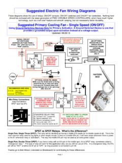
9 Nail flashing directly to the roof in four places on the : TURN OFF ELECTRICAL HOUSE CURRENT AT SERVICE ENTRANCE BEFORE wiring . INSTALLATION WORK AND ELECTRICAL wiring MUST BE DONE BY A QUALIFIED PERSON(S) IN ACCORDANCE WITH ALL APPLICABLE CODES AND STANDARDS, INCLUDING THE NATIONAL ELECTRICAL Remove the thermostat wiring box cover plate. Bring the power cable at least 6 into the ventilator wiring box. Fasten to box with appropriate BOXMASTERON-OFFSWITCHBLKGRDWHTBLKWHTGRDT OMOTORTHERMOSTAT120 VOLTSLINE INWHITEGROUND TOSWITCH BOXBLACKMASTERON-OFFSWITCH2. For standard installation, connect the two leads in the thermostat wiring box to the two power leads.
10 Attach ground wire from the power cable to the GREEN ground screw in the 5 MODEL 345 wiring (CONTINUED)MOTORVENTILATORWIRING BOXTHERMOSTATBY-PASSSWITCHBLKGRDWHTBLKWH TGRDTOMOTORTHERMOSTAT120 VOLTSLINE INWHITEGROUND TOSWITCH BOXBLACKMASTERON-OFFSWITCHMASTERON-OFFSW ITCHREDBLACKREDTHERMOSTATBY-PASS SWITCH(should normally bein OFF position)This diagram shows how to by-pass the thermostat to turn the ventilator ON or OFF Replace the metal cover plate over the thermostat wiring box and fasten The thermostat setting determines the temperature at wich the ventilator turns on . The ventilator automatically turns off when the attic temperature is 8 C (10 F) lower than the thermostat setting.


![Subject: [MB] 1987 W126 intermittent climate …](/cache/preview/7/f/6/6/5/e/d/b/thumb-7f665edb16651b024a9bdd56ab210f94.jpg)