Transcription of PAN 22 Mechanical Sliding Calliper Disc Brake …
1 PAN 22 Mechanical Sliding Calliper disc BRAKEASSEMBLY AND maintenance INSTRUCTIONSPAN 22 Mechanical Sliding Calliper disc BRAKEA ssembly and maintenance InstructionsFifth editionThis publication is not subject to an updating will find the current version 2013 WABCO Europe BVBA All rights reservedSubject to change without noticeVersion 1 (en)815 010 066 32 PAN 221 Important instructions and safety instructions .. notes .. instructions .. Risk of accidents .. Risk of injury .. and maintenance instructions .. 42 Description of the mechanically operated floating Calliper disc Brake .. 53 Checking the Brake .. the adjustment .. the Brake linings.. Optical indication of the wear limit .. the Brake discs.. Checking the condition of the Brake disc .. Checking the disc runout .. the bearing play of the guide pins.. 124 Replacing the Brake linings.
2 The Brake linings .. the protection caps and the ability of the Brake Calliper to move .. the Brake linings .. 165 Replacing the Brake .. the Brake .. the Brake .. 196 Replacing the seals .. the protective caps and bushings of the guide pins .. Disassembly .. assembly .. the protective cap of the adjuster screw .. Removing the protective cap.. Fitting the protective cap .. the protection cap on the adjuster screw hexhead.. Removing the protective cap.. Fitting the protective cap .. 287 Replacing the Brake cylinder .. the Brake cylinder .. the Brake cylinder .. 308 Annex .. tools .. across flats and tightening torques . view of the replacement parts .. of replacement parts anddisposal .. Procurement of replacement parts .. Disposal of the Brake parts .. 361 Contents31 PAN 22 Important instructions and safetyinstructions1 Important instructions and safety InformationThis publication describes the maintenance and repair of the PAN 22 disc brakes including the individual operations and work processes required to replace components using available repair Brake product numbers:This publication is directed at trained service technicians employed at workshops for commercial vehicles.
3 Before you begin with maintenance , repair, replacing a part etc., carefully read all the safety instructions as well as the repair and maintenance instructions included this publication. These instructions must be observed to avoid personal injury and/or material damage. WABCO only guarantees the safety, reliability and performance of its products and systems if all instructions , notes and safety instructions are you perform any work on the vehicle (repair, maintenance , replacing parts, etc.), you must ensure the following: Only trained and qualified personnel may perform repairs on the vehicle. Always follow the specifications and instructions of the axle or vehicle manufacturer. Always comply with the Company and national accident prevention guidelines and Health and Safety regulations. Wear suitable protective clothing as the situation requires. The workplace has to be dry, as well as sufficiently lit and Danger of accidentsWARNING!
4 Reduced braking effect or Brake failure Regularly check the wear limits of Brake linings and Brake discs. Replace worn, scorched, glazed, or oily Brake linings immediately. Immediately replace worn or damaged Brake discs. Always replace Brake linings by axle and use a new retaining system for Brake linings and pressure !Rolling vehicle Position the vehicle on an even surface and secure it against rolling away with Brake wedges. Only use approved devices to jack up and secure the vehicle. Make sure that the transmission is in neutral and the hand Brake has been !Rolling vehicle Make sure that the release screw of the spring Brake cylinder is threaded completely in after completing the maintenance and installation work and check the functionality of the parking Risk of injuryCAUTION!Hazardous dusts Do not clean any soiled areas of the Brake with compressed air or other high-pressure !
5 Heavy load A second technician must assist during removal and installation of the ! Brake action while working on the Brake Attach a clearly marked note on the steering wheel saying that work is being performed on the vehicle and that the Brake must not be 225 00740 225 00840 225 01140 225 01240 225 01540 225 016640 225 022 0640 225 023 0640 225 025 0640 225 026 0640 225 027 0640 225 028 0640 225 030 0640 225 031 0640 225 032 0640 225 033 0640 225 040 0640 225 041 0640 225 042 0640 225 043 0640 225 046 0640 225 047 0640 225 048 0640 225 049 0640 225 050 0640 225 051 0640 225 052 0640 225 053 0640 225 054 0640 225 055 0640 225 056 0640 225 057 0640 225 058 0640 225 059 0640 225 060 0640 225 061 0640 225 062 0640 225 063 041 PAN 22 Important instructions and safety instructionsCAUTION!Crushing of fingers Only grip the Brake on the outside with your hands while moving the Brake Calliper or working on the Brake .
6 Do not use motor-driven screw or torque tools!CAUTION! Falling Brake parts and high tightening and loosening torques Use suitable equipment, such as a vice, to clamp the Brake when performing repairs on the Brake outside the and maintenance instructionsFor good handling and good braking characteristics it is essential that the disc Brake is in flawless technical condition. If cast parts have been heavily damaged or are severely worn, (cracks for example), replace the entire Brake following the instructions . Never use the lining retainer (38) as a grab handle or for fastening a lifting device, because the retainer can be damaged in the process. Do not open the Brake Calliper with the clamping unit and do not loosen the retaining screws on the Calliper cover. Do not apply the Brake when Brake linings have been removed. Do not use compressed air or other high-pressure devices when cleaning the Brake or the vehicle.
7 This may result in the risk of personal injury or hazardous dusts. Rubber parts of the Brake could also be damaged. Only use original WABCO parts and approved Brake linings and retaining systems for Brake linings and pressure plates. An exploded view of replacement parts is found in the annex of this document (see chapter Exploded view of the replacement parts , page 35). Only use grease contained in the repair kits. Perform the repair work using only the recommended tools (see chapter WABCO tools , page 32). Do not use motor-driven screw or torque tools! Tighten screws and nuts only with the specified spanners, applying only the specified tightening torque; refer to the table in Annex (see chapter Widths across flats and tightening torques , page 33) for the corresponding positions. Perform a concluding roller test stand test having completed the repairs.
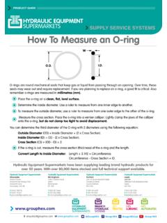
8 If no roller test stand is available, conduct a test drive with Brake action tests. Do not perform full braking, with the exception of emergency braking, during the first 50 km after new Brake linings have been fitted. Also avoid continuous braking over longer periods. Ensure that the driver of the vehicle is 22 Description of the Mechanical slidingcalliper disc brake2 Description of the Mechanical Sliding Calliper disc brakeThe PAN 22 Brake is a pneumatic one-piston Brake . It is designed for use in commercial vehicles and trailers on front and rear axle as service, auxiliary and parking brakes for " wheel rims. It is actuated mechanically via a diaphragm Brake cylinder or a spring Brake actuator. The latter is fitted directly onto the Brake Calliper , thereby reducing the overall axial length of the Brake . This enables optimal utilisation of the installation entire disc Brake consists of Brake cylinder, Brake Calliper (1), and Brake anchor plate (2).
9 disc brake1 Brake calliper2 Brake anchor plateArrowBrake Calliper shifting directionsFunctional descriptionMore information is provided in the illustrations movement of the Brake Calliper (1) occurs on the guide pins (8, 9) of the Brake carrier (2). The Brake linings (35, 36) are guided and supported axially movable in the Brake carrier. The Brake lining support is implemented by means of a retainer (38) and hold-down springs (37).The radially open design of the Brake Calliper enables simple and quick Brake lining replacements. Linings with a large wear volume are used in order to prolong the replacement compensate the wear of the linings, the actuating mechanism of the Brake is equipped with a force-dependent, stageless and automatic adjuster mechanism. This mechanism maintains a preset clearance regardless of load and operating conditions. This, together with the stable and stiff construction of the Brake Calliper , results in safe control of the pedal travel and increases the reserve of travel for emergency rubber parts and the grease fillings are maintenance -free except when disc Brake is optionally equipped with an electrical wear indicator (threshold indicator).
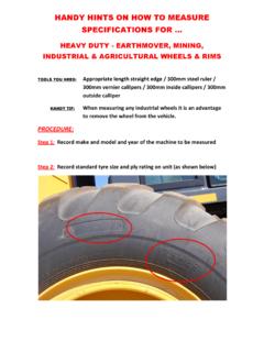
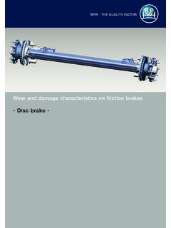
10 When the indicator in the vehicle lights up, the residual lining thickness has been reached. It is necessary to drive the vehicle to a workshop for the Brake linings to be 22 Description of the Mechanical Sliding Calliper disc view and sectional view (left Brake )1 Brake calliper2 Brake anchor plate6 Allen screws8 Guide pin (long)9 Guide pin (short)11 Closing cover (short) Closing cover (long)13 Protection cap of the adjuster19 Pressure plate22 Hexagon of the adjuster35 Brake lining rim side36 Brake lining cylinder side37 Hold-down spring38 Lining retainer39 Hexagon screw40 Cable guide with wear indicator41 Retaining clipAForward driving, direction of rotation72 PAN 22 Description of the Mechanical slidingcalliper disc view and sectional view (left Brake )1 Brake calliper2 Brake anchor plate5 Protection caps for guide Closing cover (long)12 Sealing plug for adjustment19 Pressure plate35 Brake lining rim side36 Brake lining cylinder side37 Hold-down spring38 Lining retainer39 Hexagon screwAForward driving, direction of rotation83 PAN 22 Checking the brake3 Checking the brakeCAUTION!