Transcription of Part Number: 815W0100 INSTALLATION …
1 'SBNJOH4 JMM 'MBTIJOH 5 BQF 4 JMM 'MBTIJOH 5 BQF /BJMJOH 'JO8 BUFS3 FTJTUJWF #BSSJFS4 IFBUIJOH5PQ'MBTIJOH5 BQF'JO$PSOFS%PPS 5PQ%PPS #PUUPN4 JEF'MBTIJOH5 BQF4 JEF'MBTIJOH5 BQF$PSOFS'MBTIJOH5 BQF$PSOFS'MBTIJOH5 BQF0 QUJPOBM /BJMJOH 'JO4 JMM 4 VQQPSUINSTALLATION INSTRUCTION - INSTRUCCIONES DE INSTALACION FOR CLAD HINGED PATIO DOOR WITH OR WITHOUT ADJUSTABLE HINGESPARA DE BISAGRA PARA PATIOA lways read the Pella Limited Warranty before purchasing or installing Pella products. By installing this product, you are acknowledging that this Limited Warranty is part of the terms of the sale. Failure to comply with all Pella INSTALLATION and maintenance instructions may void your Pella product warranty. See Limited Warranty for complete details at Lea las instrucciones en espa ol en el reverso.
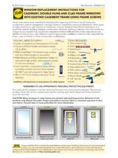
2 These instructions were developed and tested for use with typical wood frame wall construction in a wall system designed to manage water. These instructions are not to be used with any other construction method. INSTALLATION instructions for use with other construction methods, multiple units or bow and bay windows, may be obtained from Pella Corporation or a local Pella retailer, or by visiting Building designs, construction methods, building materials, and site conditions unique to your project may require an INSTALLATION method different from these instructions and additional care. Determining the appropriate INSTALLATION method is the responsibility of you, your architect, or construction TO USE APPROPRIATE PERSONAL PROTECTIVE WILL NEED TO SUPPLY:TOOLS REQUIRED: Cedar or Impervious shims/spacers (12 to 20) 2" galvanized roofing nails (1/4 lb.)
3 1 16d nail Closed cell foam backer rod/sealant backer (20 to 35 ft.) Pella SmartFlash foil backed butyl window anddoor flashing tape or equivalent High quality exterior grade polyurethane or silicone sealant (2 to 3 tubes per door) Great Stuff Window and Door Insulating Foam Sealant by the Dow Chemical Company or equivalent low pressure polyurethane window and door foam - DO NOT use high pressure or latex foams Pella aluminum sill support or 2 x 4 wood blocking Interior trim and/or jamb extensions (15 to 40 ft.) Tape measure Level Square Hammer Stapler Scissors or utility knife Screwdrivers (#2 Phillips and small flat blade) 1/8" Allen wrench Drill Sealant gun4&"-"/54&"-"/5 Part Number: 815W0100C.
4 Cut the water resistive barrier. A. Verify the opening is plumb and : It is critical that the bottom is Verify the door will fit the opening. Measure all four sides of the opening to make sure it is 3/4" larger than the door in width and 1/2" larger in height. On larger openings measure the width and height in several places to ensure the header or studs are not : 1-1/2" or more of solid wood blocking is required around the perimeter of the opening. Fix any problems with the rough opening before ROUGH OPENING PREPARATIOND. Fold the water resistive barrier (1D). Fold side flaps into the opening and staple to inside wall. Fold top flap up and temporarily fasten with flashing tape.*OUFSJPS *OUFSJPS UI DVU.
5 BLF B DVU VQ GSPN FBDI UPQ DPSOFS BU B BOHMF UP BMMPX UIF XBUFS SFTJTUJWF CBSSJFS UP CF MBQQFE PWFS UIF mO BU UIF IFBE PG UIF EPPS TU DVU OEDVU SE DVU8 BUFS 3 FTJTUJWF #BSSJFS &YUFSJPS 1" 1/2" 1/2" 6" 1E1F1" 1G1HE. Apply sill flashing tape #1. Cut a piece of flashing tape 12 longer than the opening width. Apply at the bottom of the opening as shown (1E) so it overhangs 1 to the : The tape is cut 12 longer than the width so that it will extend 6 up each side of the Tab the sill flashing tape and fold. Cut 1 wide tabs at each corner (1/2 from each side of corner) (1F). Fold tape to the exterior and press firmly to adhere it to the water resistive Apply sill flashing tape #2. Cut a piece of flashing tape 12 longer than the opening width.
6 Apply at the bottom, overlapping tape #1 by at least 1 . DO NOT allow the tape to extend past the interior face of the framing (1G). In-swing doors: If the wall depth is greater than 5 , add a third piece of flashing tape. The flashing tape should come to within 1 of the interior face of the : The flashing tape may not fully cover the framing members. When using the optional fin at the bottom of the door, do not install the aluminum sill support or wood blocking until after the doors have been installed in the rough Attach the aluminum sill support or wood blocking to the exterior of the box plate to support the edge of the door sill. Place the sill support flush with the Remove plastic wrap and cardboard packaging from door.
7 DO NOT remove plastic shipping spacers. The shipping spacers will help keep the door square during INSTALLATION . DO NOT unlock or open the door until it is fully : If screens, grilles or hardware are removed from the door at this time, label them and store them in a protected Fold out INSTALLATION fin to 90 . Be careful not to remove or tear the fin : If the fin is not at 90 , the door will not line up correctly on the interior. If using the optional fin at the sill, apply the fin and fin corners, then proceed to Step D. Sealant lines from Step C are not required when using the optional fin at the Place three 3/8" beads of sealant. The first bead should be approximately 3/4" from the exterior of the rough opening, the second bead should be placed so it is under the wood interior threshold of the door.
8 Placement will vary depending on wall thickness and door type. Place a third bead of sealant in the groove of the sill support or 1/4" from the exterior edge of the wood AND FASTENING THE DOOR&YUFSJPS &YUFSJPS 2 CInterior 2E2E2E120304050607023 INCHESmm2FF. Check the interior reveal. Make sure the measurement from the interior face of the door to the interior face of the wall is equal at several points around the : If the dimensions are not equal, check to make sure the fins are folded out to 90 at all OR MORE PEOPLE WILL BE REQUIRED FOR THE FOLLOWING STEPS. D. Insert the door from the exterior of the building. DO NOT slide the bottom of the door into the opening. Sliding will damage the sealant lines.
9 Place the bottom of the door at the bottom of the opening, then tilt the top into position. Center the door between the sides of the opening to allow clearance for shimming, and insert one roofing nail in the first hole from the corner on each end of the top nailing fin. These are used to hold the door in place while shimming it plumb and Plumb and square door. Place shims at each hinge and lock strike location between the door and the sides of the opening. Insert shims in other locations as needed starting up 6 from the bottom of the door to square it in the opening. Make sure the reveal around the door(s) is equal. On double doors, make sure the panels are even across the : On center latch double doors the lock strike will not be shimmed since it is located in the center of the unit.
10 DO NOT over Check door operation. Open and close the door to check for proper operation. Make sure the door will latch : If there are any problems with the operation, check to confirm the door frame is installed plumb, level and square. If the reveal between the door panel(s) and frame is not even, adjustments may be made: Doors without adjustable hinges: Plastic shims located behind the hinges may be removed to adjust the reveal between the door panel and door frame. Additional hinge shims may be added if : Doors with adjustable hinges will have a (+)(-) on the door panel hinge leaf to indicate possible adjustments and doors without adjustable hinges do not have adjustment indicators. Adjustable hinges are not designed to make up for failure to install the door frame correctly.