Transcription of PART ONE: INTRODUCTION TO TRIAXIAL TESTING …
1 What is TRIAXIAL TESTING ? part 1of 3 Published on the GDS website ONE: INTRODUCTION TO TRIAXIAL TESTINGP repared by Dr Sean Rees, Geotechnical Specialist at GDS InstrumentsOverview: This three part series has been written to introduce one of the most versatile tests in the geotechnical laboratory the TRIAXIAL test. The papers provide a detailed INTRODUCTION to the subject of TRIAXIAL TESTING , including the many variations available for assessing soil response across a range of engineering applications. The series is split into the following topics:1.
2 INTRODUCTION to TRIAXIAL Advanced TRIAXIAL TESTING ( part 2 is due to be released May 2013 - visit for more info).3. Dynamic TRIAXIAL paper provides an INTRODUCTION to the TRIAXIAL test, explaining why the test is performed, the stress state of a tested soil, required test system components, and the general procedure for running a TRIAXIAL test. It assumes a basic knowledge of soil mechanics for those readers unfamiliar with some terms in this paper, it is recommended they revisit part One of the GDS INTRODUCTION to Soil & Rock TESTING series, which briefly covers the key terminology and engineering parameters discussed conduct a TRIAXIAL test?
3 The TRIAXIAL test is one of the most versatile and widely performed geotechnical laboratory tests, allowing the shear strength and stiffness of soil and rock to be determined for use in geotechnical design. Advantages over simpler procedures, such as the direct shear test, include the ability to control specimen drainage and take measurements of pore water pressures. Primary parameters obtained from the test may include the angle of shearing resistance , cohesion c , and undrained shear strength cu, although other parameters such as the shear stiffness G, compression index Cc, and permeability k may also be determined.
4 Figure 1 gives an example of the engineering application of the test here TRIAXIAL compression provides strength information at the top of a cut slope, whilst TRIAXIAL extension allows parameters for soil elements at the slope base to be 1 Example of an engineering application of the TRIAXIAL does a TRIAXIAL test involve?The TRIAXIAL test typically involves placing a cylindrical specimen of soil, ranging from 38mm to 100mm diameter, into a cell that can be pressurised.
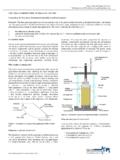
5 Most specimens have an approximate 2:1 height-to-diameter ratio, and are sealed within a rubber membrane. Following this initial preparation the specimen is saturated, consolidated, and sheared, allowing the soil response to be observed under conditions that may approximate those in-situ. During the shear stage the soil is loaded axially, either in compression, or less-commonly in extension. The general set-up of a TRIAXIAL specimen inside a TRIAXIAL cell is shown in Figure 2 General set-up of a soil specimen inside a TRIAXIAL are the types of TRIAXIAL test?
6 There are three primary TRIAXIAL tests conducted in the laboratory, each allowing the soil response for differing engineering applications to be observed. These are: Unconsolidated Undrained test (UU) Consolidated Undrained test (CU) Consolidated Drained test (CD)GDS INTRODUCTION to TRIAXIAL TESTING : part 11 What is TRIAXIAL TESTING ? part 1of 3 Published on the GDS website INTRODUCTION to TRIAXIAL TESTING : part 1 The unconsolidated undrained (UU) test is the simplest and fastest procedure, with soil specimens loaded whilst only total stresses are controlled and recorded.
7 This allows the undrained shear strength cu to be determined, which is suitable for assessing soil stability in the short-term ( during or directly following a construction project). Note this test is generally performed on cohesive soil consolidated drained (CD) test on the other hand is applicable to describing long-term loading response, providing strength parameters determined under effective stress control ( and c ). The test can however take a significant time to complete when using cohesive soil, given the shear rate must be slow enough to allow negligible pore water pressure the consolidated undrained (CU) test is the most common TRIAXIAL procedure, as it allows strength parameters to be determined based on the effective stresses ( and c ) whilst permitting a faster rate of shearing compared with the CD test.
8 This is achieved by recording the excess pore pressure change within the specimen as shearing takes STATE DURING A TRIAXIAL TESTThe stresses applied to a soil or rock specimen when running a TRIAXIAL compression test are displayed in Figure 3. The confining stress c is applied by pressurising the cell fluid surrounding the specimen it is equal to the radial stress r, or minor principal stress 3. The deviator stress q is generated by applying an axial strain a to the soil the deviator stress acts in addition to the confining stress in the axial direction, with these combined stresses equal to the axial stress a, or major principal stress 1.
9 The stress state is said to be isotropic when 1 = 3, and anisotropic when 1 3 Specimen stress state during TRIAXIAL the principal stress directions rotate by 90 when a TRIAXIAL extension test is performed in such a case the radial stress corresponds to the major principal stress direction, with the axial stress providing the minor principal SYSTEM COMPONENTSTo perform a TRIAXIAL test the system must contain a number of components to enable the desired specimen stress state to be reached, and shear the specimen whilst recording the soil response.
10 Table 1 lists each primary component of a GDS TRIAXIAL system, along with its main function. A complete system diagram is presented in Figure 1 Primary components of a GDS TRIAXIAL automated functionTriaxial cellHouse the specimen and cell fluidPedestal & top-capProvide specimen seating and drainage portsRubber membrane, O-rings & porous discsSeal the specimen from the cell fluid, allowing control over the effective stress and drainageCell pressure / volume controllerApply confining stress to the specimen ( c = 3)