Transcription of Photovoltaic MOSFET Driver with Integrated Fast Turn-Off ...
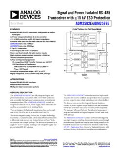
1 Semiconductors Rev. , 16-Dec-20191 Document Number: 83469 For technical questions, contact: DOCUMENT IS SUBJECT TO CHANGE WITHOUT NOTICE. THE PRODUCTS DESCRIBED HEREIN AND THIS DOCUMENTARE SUBJECT TO SPECIFIC DISCLAIMERS, SET FORTH AT MOSFET Driver with Integrated Fast Turn-Off , Solid-State RelayADDITIONAL RESOURCESDESCRIPTIONThe VOM1271 is a stand-alone optically isolated MOSFET Driver . Unlike conventional MOSFET drivers, which require an external power supply to provide VCC and or VDD rails to the Driver itself, the VOM1271 obtains all the required current to drive its internal circuitry from the LED current on the low voltage primary side of the isolation barrier. This saves the designer the space and cost associated with providing one or more external power supplies.
2 The VOM1271 also integrates a Turn-Off circuit internal to the component itself, thus doing away with the need for additional components in order to increase the overall switching speed by decreasing the Turn-Off time. These features, combined with a small SOP4 package, provide designers with a small footprint, highly Integrated isolated gate Driver solution for a large variety of MOSFET Driver Open circuit voltage at IF = 10 mA, V typical Short circuit current at IF = 10 mA, 15 A typical Isolation test voltage 3750 VRMS Logic compatible input High reliability Integrated rapid Turn-Off circuitry Material categorization: for definitions of compliance please see High-side Driver Solid-state relays Floating power supply power control Data acquisition ATE isolated solenoid drivers isolated high current relay drivers isolated high voltage relay driversAGENCY APPROVALS UL cUL VDE FIMKO Note For additional information on the available options refer to option information.
3 The product is available only on tape and reel4312Tu r nOffi179066_6 Design Tools333 DDD3D3D ModelsFootprintsModelsORDERING INFORMATIONVOM1 2 7 1 T PART NUMBERTAPEANDREELPACKAGEUL, cUL, Semiconductors Rev. , 16-Dec-20192 Document Number: 83469 For technical questions, contact: DOCUMENT IS SUBJECT TO CHANGE WITHOUT NOTICE. THE PRODUCTS DESCRIBED HEREIN AND THIS DOCUMENTARE SUBJECT TO SPECIFIC DISCLAIMERS, SET FORTH AT Stresses in excess of the absolute maximum ratings can cause permanent damage to the device. Functional operation of the device is not implied at these or any other conditions in excess of those given in the operational sections of this document. Exposure to absolute maximum ratings for extended periods of the time can adversely affect reliability(1)Refer to reflow profile for soldering conditions for surface mounted devices (SOP)Note Minimum and maximum values are testing requirements.
4 Typical values are characteristics of the device and are the result of engineering evaluations. Typical values are for information only and are not part of the testing requirementsFig. 1 - ton, toff Test Circuit and WaveformsABSOLUTE MAXIMUM RATINGS (Tamb = 25 C, unless otherwise specified)PARAMETERTEST CONDITIONSYMBOLVALUEUNITSSRLED continous forward currentIF50mALED reverse voltageIR 10 AVR5 VAmbient operating temperature rangeTamb-40 to +100 CStorage temperature rangeTstg-40 to +125 CPin soldering temperature (1)t = 10 sTsld260 CELECTRICAL CHARACTERISTICS (Tamb = 25 C, unless otherwise specified)PARAMETERTEST forward voltageIF = 10 circuit voltageIF = 5 VIF = 10 = 20 VIF = 30 VShort circuit currentIF = 5 AIF = 10 AIF = 20 AIF = 30 ASWITCHING CHARACTERISTICS (Tamb = 25 C, unless otherwise specified)
5 PARAMETERTEST timeCL = 200 pF, IF = 20 mA,PW = 2 ms, duty cycle = 50 %ton-53- sTurn-off timetoff-24- s1243IF10 M TurnOFF200 pFVOC, ISCVOM1271 InputOutput10 %90 % Semiconductors Rev. , 16-Dec-20193 Document Number: 83469 For technical questions, contact: DOCUMENT IS SUBJECT TO CHANGE WITHOUT NOTICE. THE PRODUCTS DESCRIBED HEREIN AND THIS DOCUMENTARE SUBJECT TO SPECIFIC DISCLAIMERS, SET FORTH AT As per DIN EN 60747-5-5, , this optocoupler is suitable for safe electrical insulation only within the safety ratings. Compliance with the safety ratings shall be ensured by means of protective circuitsTYPICAL CHARACTERISTICS (Tamb = 25 C, unless otherwise specified)Fig. 2 - Output Open Circuit Voltage vs. LED CurrentFig. 3 - Output Short-Circuit Current vs. Ambient TemperatureFig. 4 - Output Open Circuit Voltage vs.
6 Ambient TemperatureFig. 5 - ton, toff vs. LED CurrentSAFETY AND INSULATION RATINGS PARAMETERTEST CONDITIONSYMBOLVALUEUNITC limatic classificationAccording to IEC 68 part 155 / 110 / 21 Pollution degreeAccording to DIN VDE 01092 Comparative tracking index Insulation group IIIaCTI175 Maximum rated withstanding isolation voltageAccording to UL1577, t = 1 min VISO3750 VRMSM aximum transient isolation voltageAccording to DIN EN 60747-5-5 VIOTM6000 VpeakMaximum repetitive peak isolation voltageAccording to DIN EN 60747-5-5 VIORM707 VpeakIsolation resistanceTamb = 25 C, VIO = 500 VRIO 1012 Tamb = 100 C, VIO = 500 VRIO 1011 Output safety power PSO350mWInput safety current ISI150mAInput safety temperature TS175 CCreepage distanceSOP-4 5mmClearance distanceSOP-4 5mmInsulation thickness DTI 10 0204050 VOC (V)IF (mA)
7 9876543211030RL = 1 M RL = 500 k 1535455250 60 -40040100 ISC ( A)Ambient Temperature ( C)5040302010-20206080IF = 30 mAIF = 5 mAIF = 10 mA4 12-40040100 VOC (V)Ambient Temperature ( C)1086-202060IF = 30 mAIF = 5 mA80IF = 10 mA119750 600 0102050ton, toff ( s)IF (mA) Semiconductors Rev. , 16-Dec-20194 Document Number: 83469 For technical questions, contact: DOCUMENT IS SUBJECT TO CHANGE WITHOUT NOTICE. THE PRODUCTS DESCRIBED HEREIN AND THIS DOCUMENTARE SUBJECT TO SPECIFIC DISCLAIMERS, SET FORTH AT 6 - LED Reverse Current vs. Reverse VoltageFig. 7 - LED Forward Voltage vs. LED Forward CurrentFig. 8 - Short Circuit Output Current Circuit Output VoltageAPPLICATION DESCRIPTIONFig. 9 illustrates a standard isolated MOSFET Driver such as Vishay s VO1263. Though these parts are generally capable of supplying higher output current, they lack Integrated fast Turn-Off circuitry.
8 Thus, if high Turn-Off speed is required. external circuitry needs to be provided, as illustrated in Fig. 10 illustrates the ability to do away with external Turn-Off circuitry with the VOM1271, by taking advantage of the VOM1271 s Integrated Turn-Off circuitry. Fig. 9 - Typical MOSFET Driver Application without Integrated Fast Turn-Off0 20222425IR ( A)VR (V) C0 0102050VF (V)IF (mA) C0 C25 C0 10 20 30 40 50 60 70 80 0 1 2 3 4 5 6 7 8 9 10 ISC ( A) VOC (V) IF = 45 mAIF = 5 mAIF = 15 mAIF = 35 mAIF = 25 mAP-channelJFET2 M Channel 1controlSwitch 1N-channelMOSFETsTu r Semiconductors Rev. , 16-Dec-20195 Document Number: 83469 For technical questions, contact: DOCUMENT IS SUBJECT TO CHANGE WITHOUT NOTICE. THE PRODUCTS DESCRIBED HEREIN AND THIS DOCUMENTARE SUBJECT TO SPECIFIC DISCLAIMERS, SET FORTH AT 10 - Typical MOSFET Driver Applications with Integrated Fast Turn-OffPACKAGE DIMENSIONS in millimetersPACKAGE MARKING (example)Bidirectional MOSFET Driver Application Single MOSFET Driver Application1243+-VOM1271 TURNOFF1243+-TURNOFFVOM1271M1271V YWW68 Pin One Semiconductors Rev.
9 , 16-Dec-20196 Document Number: 83469 For technical questions, contact: DOCUMENT IS SUBJECT TO CHANGE WITHOUT NOTICE. THE PRODUCTS DESCRIBED HEREIN AND THIS DOCUMENTARE SUBJECT TO SPECIFIC DISCLAIMERS, SET FORTH AT AND REEL PACKAGINGD imensions in millimetersFig. 11 - Tape and Reel Shipping Medium(EIA-481, revision A, and IEC 60286), 2000 units per reelFig. 12 - Tape DimensionsSOLDER PROFILESFig. 13 - Lead (Pb)-free Reflow Solder ProfileAccording to J-STD-020 for SMD DevicesHANDLING AND STORAGE CONDITIONSESD level: HBM class 2 Floor life: unlimitedConditions: Tamb < 30 C, RH < 60 %Moisture sensitivity level 1, according to J-STD-020 ESD stickerTape slotin core330(13")Regular, specialor bar code + CMax. 260 C217 C255 C198411010010001000001002003000501001502 00300 Axis Title1st line2nd line2nd lineTemperature ( C)Time (s)50150250250245 CMax.
10 100 sMax. 30 sMax. 120 sMax. ramp down 6 C/sMax. ramp up 3 C/sLegal Disclaimer Revision: 01-Jan-20221 Document Number: 91000 Disclaimer ALL PRODUCT, PRODUCT SPECIFICATIONS AND DATA ARE SUBJECT TO CHANGE WITHOUT NOTICE TO IMPROVE RELIABILITY, FUNCTION OR DESIGN OR OTHERWISE. Vishay Intertechnology, Inc., its affiliates, agents, and employees, and all persons acting on its or their behalf (collectively, Vishay ), disclaim any and all liability for any errors, inaccuracies or incompleteness contained in any datasheet or in any other disclosure relating to any makes no warranty, representation or guarantee regarding the suitability of the products for any particular purpose or the continuing production of any product. To the maximum extent permitted by applicable law, Vishay disclaims (i) any and all liability arising out of the application or use of any product, (ii) any and all liability, including without limitation special, consequential or incidental damages, and (iii) any and all implied warranties, including warranties of fitness for particular purpose, non-infringement and regarding the suitability of products for certain types of applications are based on Vishay's knowledge of typical requirements that are often placed on Vishay products in generic applications.