Transcription of Photovoltaic System Overcurrent Protection
1 Photovoltaic System Overcurrent ProtectionIntroductionSolar Photovoltaic (PV) systems have, overthe last fifty years, evolved into a mature, sustainable and adaptive technology is improving as solar cellsincrease in efficiency and modules attainbetter aesthetic a result, solar power is gaining moreacceptance and is becoming an increasingly cost-effective and clean alternative to conventional energy installations and demand for PV systems increases so does the need for effective electrical systems, as with all electrical power systems, must have appropriateovercurrent Protection for equipment and Bussmann (the world leader inovercurrent Protection products) has developed a revolutionary new fuse link forprotecting Photovoltaic development was implementedthrough coordinated research and testingwith leading Solar Panel/Solar System Protection System from Cooper BussmannPhotovoltaic System Overcurrent ProtectionlAnumber of PV panels in series is termed a stringlAnumber of strings in parallel is termed an array2 2009 Cooper BussmannSolar Power generation systems are made ofPhotovoltaic cells and Power inverters.
2 The Photovoltaic cells utilise the power of sunlight toconverters photons to clean DC (Direct Current) Electricity generated by the Solar Cells is thenfed into a Power Inverter (PV inverter) that convertsand regulates the DC source into usable AC AC power can then be used locally for specificremote equipment, residential homes or fed directlyback into the power grid and used as environmentally clean content of sunlight: sunlight has an energycontent of 1kW (1000 watts) per square typical Solar Panel achieves between 10% and15% efficiency Solar Power Systems workThe voltage output of a Solar Panel/Array is defined bythe number of individual cells in series. An individualpanel (see Fig. 1) is made up of a series string of Photovoltaic there is a push for utilizing higher voltages(trending to 1000 Vdc and above).lA number of PV panels in series is termed a stringlA number of strings in parallel is called an arrayThe vast majority of large Solar Farms in NorthAmerica are 600 Vdc, but following the lead fromEurope to increase voltages up to 1000 Vdc to achievemore Power Protection System from Cooper BussmannV+3 2009 Cooper BussmannFigure 1 Variations of Solar Panel OutputOvercurrent Protection of PV SystemsThe National Electrical Code defines the maximum circuit current as 125% ofthe short-circuit current of the PV module (Isc).
3 The conductors and the Overcurrent protective device are then sized at 125% of the maximum circuitcurrent or x Isc. Additionally, International standards such as BS EN7671 Sec 712 for Solar Photovoltaic (PV) Power Supply systems specify that conductors current carrying ability must be equal to or greater than xIscSTC* at any location. The Iscis published by the PV module manufacturerson datasheets. The Iscis typically only 110-115% of the maximum power current (Ipm) of the PV means that unlike typical grid connected AC systems, the available shortcircuit current is limited and the Overcurrent protective devices will need tooperate effectively on low levels of fault current. For this reason CooperBussmann has conducted extensive research and development of fuses thatare specifically designed and tested to safely protect PV systems with highDC voltages and low fault currents. lDCM - 600 VdclPV - 1000 Vdc*IscSTC: The Electrical data applies under Standard Test Conditions (STC): Radiation 1000 W/m2with a spectrum of AM and at cell temperature of Fuse - 1000 VdcThe most widely used Solar Panels for systems greater than20kW are the 4 , 5 and 6 Poly-crystalline silicon Silicon type panel can achieve up to approx maximum power current per panel.
4 Again there is no specificpreference as economics also play a role in the selection ofSolar Cell word of caution is do not assume all 4 , 5 and 6 Solarpanel designs are equal between different manufacturers. The maximum power output current of the panels can vary asmuch as 35% between manufacturers of equal solar cell dimension always select proper conductors/fusesbased on the specific Isc* characteristics of the manufacturersspecification.*Isc: Short circuit current 4 2009 Cooper BussmannDCM - 600 VdcPhotovoltaic System Overcurrent ProtectionDepending on the desired capacity of the PV System , theremay be several PV strings connected in parallel to achievehigher currents and subsequently more power. PV systems that have three or more strings connected in parallel need to have each string protected (systems thathave less than three strings will not generate enough faultcurrent to damage the conductors/equipment and therefore do not present a safety hazard as long as theconductor was sized properly based on local code requirements).
5 Where three or more strings are connected in parallel a fuseon each string will protect the conductors from damage andhelp minimise any safety hazards. It will also isolate the faulted string so that the rest of the PV System can continueto generate of ConductorslIsolate damaged PV modulesSelecting Fuse Links for PV String Protection5 2009 Cooper BussmannDefine Solar Panel SpeclIpmlIsclMax System VoltageDefine number of parallelsolar panels/stringsN = parallel panels/stringDefine conductor/fuse size per x Isc= I conductor/fuse rating withstand @ 80oC(Panel Back plane temperature influence,ambient temp influence)Ipm:current at maximum powerIsc:short-circuit currentDoes array max Iscexceed continuouscurrent rating of conductor selected?Max Array Isc= (N-1) *IscPV String Fuse In= x IscSelect equal to or next higher std fuse rating PV String Fuse Vn=> Max System VoltageApply PV fuse to + and - StringsNo PV StringFusing requiredPV Fuse Selection Flow-ChartggggggYe sNoNoFuse Rating for PV ApplicationsOnce it has been determined that maximum short-circuit current ([N-1]*Isc) exceeds continuous current rating of conductor, follow the recommendations of selecting the proper PV string 1: Solar Panel String FusingIsc= System Voltage = 1000 Vdc (max value of series panels)Conductor Size Formula = * Isc= * = Size = 14 AWG or @ 80oCN = 4 (4parallel Solar Panel Strings)Array Max Isc= (N-1) * Isc= (4-1) * = Max Iscis greater than conductor withstand, therefore string fuses are requiredIn= x Isc(individual panel only) = min fuse ratingSelect next higher std rating of 10A.
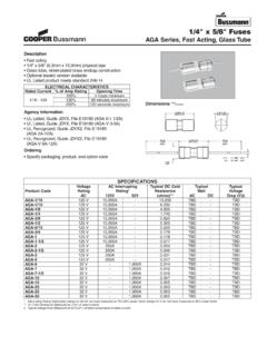
6 PV-10A10 FFuse selected will protect selected conductorMin wire size: 14 AWG or @ 80oCModule DescriptionCell TypePolycrystalline SiliconCell Size125mm2(5")No of Cells and Connection72 in SeriesMaximum System Voltage1,000 VdcElectrical DataMaximum Power Voltage (Vpm) Circuit Voltage (Voc) Power Current (Ipm) Circuit Current (Isc) Solar Panel Specification6 2009 Cooper BussmannPhotovoltaic System Overcurrent Protection7 2009 Cooper BussmannDCM Fuses Technical Data1/10 - 30A/600 VdcStandards/Approvalsll UL listed STD 248-14 (File E19180, Guide JDYX)ll CSA Certified NO (Class 1422-01, File 53787)Ratingsll Rated voltage: 600 VdcAmps: 1/10 to 30A Breaking capacity:100k at 600 Vac50k at 600 VdcPackagingll MOQ: 10 PackagingDimensions - inDescriptionll Full range of DC Midget in 10x38mmAC Maximum Interrupting Rating of 100kA at 600 Vac DC Maximum Interrupting Rating at 50kA at 600 VdcDC Minimum Interrupting Rating of 200% rated current at 600 VdcCatalogue Symbolll DCMType of Operationll Fast-acting 1/10 to 30 AFuse holdersRecommended fuse blocks/fuse holders for 10x38mm fuses:- Open fuse blocks: BM Series, 3743- Finger-safe fuse holders: OPM-NG-SC3, OPM-NG-SM3, OPM-1038, CHMD Series- Panel mount fuse holders: HPF Series, HPS Series, HPG & HPD, HPM Series, HPC-D, HPS2 SeriesTime-Current Curves n8 2009 Cooper BussmannPV Fuse Link Technical Data1 - 15A/1000 VdcStandards/Approvalsll Manufactured in accordance with IEC 60269 Ratingsll Volts: 1000 VdcAmps: 1 to 6A, 8A, 10A, 12A & 15A Breaking Capacity: 33kA dcMin x Inll PV Fuse Link Coordination with.
7 4 , 5 & 6 solar cellsll Time constant (L/R): Under 1msPackagingll MOQ: 10 Packaging 100% recyclableFuse Holdersll PCB clip: 1A3400-09ll Modular fuse holder: CHM1 DDescriptionll A range of 10x38mm fuse links specifically designed for protecting Photovoltaic strings. These fuse links arecapable of interrupting low overcurrents associated with faulted Photovoltaic string arrays (reverse current, multi-array fault). Catalogue Symbol/Fixingll PV-(amp rating)A10F - Cylindricalll PV-(amp rating)A10-T - Boltll PV-(amp rating)A10-1P - Printed Circuit Boardll PV-(amp rating)A10F-2P - Printed Circuit BoardClass of Operationll gR - (PV)Dimensions - mm* Refers to fixing/mounting types, for example PV-15A10 FTime-Current CurvesPhotovoltaic System Overcurrent Protection9 2009 Cooper BussmannDescriptionll Type M fuse block for use with any 10x38 fusesCatalogue Symbolll BM SeriesDIN Rail Adapters ll DRA-1 and DRA-2 Standards/Approvalsll UL Recognized, UL 512, Guide IZLT2, File E14853ll CSA Certified No 39, Class 6225-01, File 47235ll BM603xPQ self certified for 1000 VdcFuse Block For PV and DCM Fuse Links - BM Fuse BlockDescriptionll Fuse clip for 10mm diameter fuses with end stops and straight leads 20 Amps maximumCatalogue Symbol.
8 Ll 1A3400 Fuse Clips For PV and DCM - 1A3400 SeriesDimensions - inFootprint - in (mm)A = ( )B = ( )C = (4 holes) = - ( - )For board thickness up to ( )Descriptionll The CHMD and CHM1D-PV-IEC modular fuse holders, accommodates 10x38mm fuse linksCatalogue Symbolll CHMD Series ll CHM1D-PV-IECR atingsll CHMD Series is rated at 690 Vdcll CHM1D-PV-IEC is rated at 1000 VdcStandards/Approvalsll CHMD Series UL Recognized UL512, Guide IZLT2, File E14853, CSA Certified No 39, Class 6225-01 File 47235. Approvals at 600 Vdc. ll CHM1D-PV-IEC, type test certificate of compliance with IEC 60269-1 for a rating of - mmFuse Holders For PV and DCM Fuse Links - CHMD and CHM1D-PV-IEC Modular Fuse HoldersABBCD imensions - in (mm)2 and 3 poles also availablen4-pole unit shown by way of example 2009 Cooper Bussmann UK LtdMelton Road, Burton-on-the-WoldsLE12 5TH, United Kingdom00 44 (0) 1509 882 # SOLARBROCH0909 Cooper Bussmann Products and Technical Expertise Delivered WorldwideCustomer AssistanceApplication EngineeringApplication Engineering assistance is available to allcustomers.
9 The Application Engineering team isstaffed by university-qualified electrical engineerswho are available by phone with technical and appli-cation supportUnited States:Monday Friday, 8:00 5:00 Central Engineering can be reached via phone, fax or email: Phone: 636-527-1270 Fax: 636-527-1607 E-mail: Thursday am pm GMTF riday am - pm GMTA pplication Engineering can be reached via phone,fax or email: Phone: 00 44 (0) 1509 882 699 Fax: 00 44 (0) 1509 882 794 E-mail: ResourcesVisit for the followingresources: Product cross reference Product Data Sheets Product Profiles Online catalogues for the latest United States andEuropean CataloguesCustomer Satisfaction TeamThe Cooper Bussmann Customer Satisfaction Team isavailable to answer questions regarding CooperBussmann products. Calls can be made between:United States:Monday Friday,8:00 4:30 for all US time Customer Satisfaction Team can be reached via: Phone: 636-527-3877 Toll-free fax: 800-544-2570 E-mail: and After-Hours OrdersTo accommodate time-critical needs, Cooper Bussmann offers emergency and after-hours service for next flight out or will call.
10 Customers pay only standard price for the circuit Protection device, rush freight charges and a modest emergency fee for this service. Emergency and after-hours orders should be placed through the Customer Satisfaction Team. Call: Monday Friday,8:00 4:30 Time 636-527-3877 After hours 314-995-1342 Europe:Monday-Thursday am - pm am - pm GMT The Customer Satisfaction Team can be reached via: Phone: 00 44 (0) 1509 882 600 Fax: 00 44 (0) 1509 882 786 E-mail.