Transcription of PIC18F Microcontroller Series - Elsevier.com
1 CHAPTER 2 PIC18F Microcontroller SeriesPIC16- Series microcontrollers have been around for many years. Although these areexcellent general purpose microcontrollers, they have certain limitations. For example,the program and data memory capacities are limited, the stack is small, and the interruptstructure is primitive, all interrupt sources sharing the same interrupt vector. PIC16- Series microcontrollers also do not provide direct support for advanced peripheralinterfaces such as USB, CAN bus, etc., and interfacing with such devices is not instruction set for these microcontrollers is also limited. For example, there are nomultiplication or division instructions, and branching is rather simple, being acombination Inc. has developed the PIC18 Series of microcontrollers for use in high-pin-count, high-density, and complex applications. The PIC18F microcontrollers offer cost-efficient solutions for general purpose applications written in C that use a real-timeoperating system (RTOS) and require a complex communication protocol stack such asTCP/IP, CAN, USB, or ZigBee.
2 PIC18F devices provide flash program memory in sizesfrom 8 to 128 Kbytes and data memory from 256 to 4 Kbytes, operating at a range to volts, at speeds from DC to basic features of PIC18F - Series microcontrollers are: 77 instructions PIC16 source code compatible Program memory addressing up to 2 Mbytes Data memory addressing up to DC to 40 MHz operation 8 8 hardware multiplier Interrupt priority levels 16-bit-wide instructions, 8-bit-wide data path Up to two 8-bit timers/counters Up to three 16-bit timers/counters Up to four external interrupts High current (25mA) sink/source capability Up to five capture/compare/PWM modules Master synchronous serial port module (SPI and I2C modes) Up to two USART modules Parallel slave port (PSP) Fast 10-bit analog-to-digital converter Programmable low-voltage detection (LVD) module Power-on reset (POR), power-up timer (PWRT), and oscillator start-up timer (OST) Watchdog timer (WDT) with on-chip RC oscillator In-circuit programmingIn addition, some microcontrollers in the PIC18F family offer the following specialfeatures.
3 Direct CAN bus interface Direct USB bus interface Direct LCD control interface TCP/IP interface ZigBee interface Direct motor control 2 Most devices in the PIC18F family are source compatible with each other. Table the characteristics of some of the popular devices in this family. This chapteroffers a detailed study of the PIC18 FXX2 microcontrollers. The architectures of most ofthe other microcontrollers in the PIC18F family are reader may be familiar with the programming and applications of the PIC16 Fseries. Before going into the details of the PIC18F Series , it is worthwhile to comparethe features of the PIC18F Series with those of the PIC16F following are similarities between PIC16F and PIC18F : Similar packages and pinouts Similar special function register (SFR) names and functions Similar peripheral devicesTable : The 18 FXX2 Microcontroller familyFeaturePIC18F242 PIC18F252 PIC18F442 PIC18F452 Program memory(Bytes)16K32K16K32 KData memory (Bytes)76815367681536 EEPROM (Bytes)256256256256I/O PortsA,B,CA,B,CA,B,C,D,EA,B,C,D,ETimers4 444 Interrupt sources17171818 Capture/compare/PWM 2222 Serial communicationMSSPUSARTMSSPUSARTMSSPUSART MSSPUSARTA/D converter (10-bit)5 channels5 channels8 channels8 channelsLow-voltage detectyesyesyesyesBrown-out resetyesyesyesyesPackages28-pin DIP28-pin SOIC28-pin DIP28-pin SOIC40-pin DIP44-pin PLCC44-pin TQFP40-pin DIP44-pin PLCC44-pin Microcontroller Series Subset of PIC18F instruction set Similar development toolsThe following are new with the PIC18F Series .
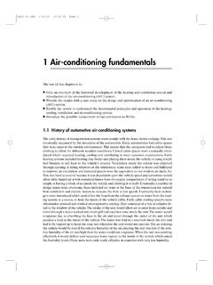
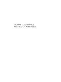
4 Number of instructions doubled 16-bit instruction word Hardware 8 8 multiplier More external interrupts Priority-based interrupts Enhanced status register Increased program and data memory size Bigger stack Phase-locked loop (PLL) clock generator Enhanced input-output port architecture Set of configuration registers Higher speed of operation Lower power PIC18 FXX2 ArchitectureAs shown in Table , the PIC18 FXX2 Series consists of four devices. PIC18F2X2microcontrollers are 28-pin devices, while PIC18F4X2 microcontrollers are 40-pin architectures of the two groups are almost identical except that the larger devices havemore input-output ports and more A/D converterchannels. In this section we shall be lookingat the architecture of the PIC18F452 Microcontroller in detail. The architectures of otherstandard PIC18F - Series microcontrollers are similar, and the knowledge gained in this sectionshould be enough to understand the operation of other PIC18F - Series pin configuration of the PIC18F452 Microcontroller (DIP package) is shown inFigure This is a 40-pin Microcontroller housed in a DIL package, with a pinconfiguration similar to the popular 2 Figure shows the internal block diagram of the PIC18F452 Microcontroller .
5 TheCPU is at the center of the diagram and consists of an 8-bit ALU, an 8-bit workingaccumulator register (WREG), and an 8 8 hardware multiplier. The higher byte andthe lower byte of a multiplication are stored in two 8-bit registers called PRODH andPRODL program counter and program memory are shown in the upper left portion ofthe diagram. Program memory addresses consist of 21 bits, capable of accessing2 Mbytes of program memory locations. The PIC18F452 has only 32 Kbytes of programmemory, which requires only 15 bits. The remaining 6 address bits are redundant andnot used. A table pointer provides access to tables and to the data stored in programmemory. The program memory contains a 31-level stack which is normally used tostore the interrupt and subroutine return data memory can be seen at the top center of the diagram. The data memory busis 12 bits wide, capable of accessing 4 Kbytes of data memory locations.
6 As we shallsee later, the data memory consists of special function registers (SFR) and generalpurpose registers, all organized in : PIC18F452 Microcontroller DIP pin Microcontroller SeriesFigure : Block diagram of the PIC18F452 2 The bottom portion of the diagram shows the timers/counters, capture/compare/PWMregisters, USART, A/D converter, and EEPROM data memory. The PIC18F452consists of: 4 timers/counters 2 capture/compare/PWM modules 2 serial communication modules 8 10-bit A/D converter channels 256 bytes EEPROMThe oscillator circuit, located at the left side of the diagram, consists of: Power-up timer Oscillator start-up timer Power-on reset Watchdog timer Brown-out reset Low-voltage programming In-circuit debugger PLL circuit Timing generation circuitThe PLL circuit is new to the PIC18F Series and provides the option of multiplying up theoscillator frequency to speed up the overall operation.
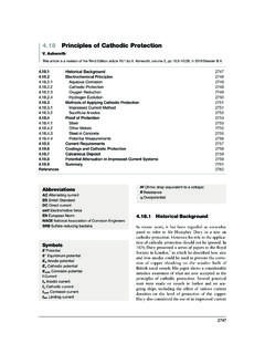
7 The watchdog timer can be used toforce a restart of the Microcontroller in the event of a program crash. The in-circuitdebugger is useful during program development and can be used to return diagnostic data,including the register values, as the Microcontroller is executing a input-output ports are located at the right side of the diagram. The PIC18F452has five parallel ports named PORTA, PORTB, PORTC, PORTD, and PORTE. Mostport pins have multiple functions. For example, PORTA pins can be used as parallelinputs-outputs or analog inputs. PORTB pins can be used as parallel inputs-outputs oras interrupt Microcontroller Program Memory OrganizationThe program memory map is shown in Figure All PIC18F devices have a 21-bitprogram counter and hence are capable of addressing 2 Mbytes of memory space. Usermemory space on the PIC18F452 Microcontroller is 00000H to 7 FFFH. Accessing anonexistent memory location (8000H to 1 FFFFFH) will cause a read of all 0s.
8 The resetvector, where the program starts after a reset, is at address 0000. Addresses 0008H andFigure : Program memory map of 20018H are reserved for the vectors of high-priority and low-priority interruptsrespectively, and interrupt service routines must be written to start at one of PIC18F Microcontroller has a 31-entry stack that is used to hold the returnaddresses for subroutine calls and interrupt processing. The stack is not part of theprogram or the data memory space. The stack is controlled by a 5-bit stack pointerwhich is initialized to 00000 after a reset. During a subroutine call (or interrupt) thestack pointer is first incremented, and the memory location it points to is written withthe contents of the program counter. During the return from a subroutine call (orinterrupt), the memory location the stack pointer has pointed to is decremented. Theprojects in this book are based on using the C language .
9 Since subroutine and interruptcall/return operations are handled automatically by the C language compiler, theiroperation is not described here in more memory is addressed in bytes, and instructions are stored as two bytes or fourbytes in program memory. The least significant byte of an instruction word is alwaysstored in an even address of the program instruction cycle consists of four cycles: A fetch cycle begins with the programcounter incrementing in Q1. In the execution cycle, the fetched instruction is latchedinto the instruction register in cycle Q1. This instruction is decoded and executed duringcycles Q2, Q3, and Q4. A data memory location is read during the Q2 cycle and writtenduring the Q4 Data Memory OrganizationThe data memory map of the PIC18F452 Microcontroller is shown in Figure Thedata memory address bus is 12 bits with the capability to address up to memory in general consists of sixteen banks, each of 256 bytes, where only 6 banksare used.
10 The PIC18F452 has 1536 bytes of data memory (6 banks 256 bytes each)occupying the lower end of the data memory. Bank switching happens automaticallywhen a high-level language compiler is used, and thus the user need not worry aboutselecting memory banks during special function register (SFR) occupies the upper half of the top memory contains registers which control operations such as peripheral devices, timers/counters, A/D converter, interrupts, and USART. Figure shows the SFR registers ofthe PIC18F452 Microcontroller The Configuration RegistersPIC18F452 microcontrollers have a set of configuration registers (PIC16-seriesmicrocontrollers had only one configuration register). Configuration registersare programmed during the programming of the flash program memory by theprogramming device. These registers are shown in Table Descriptions ofFigure : The PIC18F452 data memory 2these registers are given in Table Some of the more important configurationregisters are described in this section in CONFIG1H configuration register is at address 300001H and is used to select themicrocontroller clock sources.