Transcription of PILED FOUNDATION DESIGN & CONSTRUCTION
1 PILED FOUNDATION PILED FOUNDATION DESIGN & CONSTRUCTIONDESIGN & CONSTRUCTIONBy Ir. Dr. Gue See Sew & Ir. Chow Chee StudyzSite Visit & SI PlanningzPile DesignzPile Installation MethodszTypes of PilesContents (ContContents (Cont d)d)zPiling SupervisionzPile DamagezPiling ProblemszTypical DESIGN and CONSTRUCTION IssueszMyths in PilingzCase HistorieszConclusionsOverviewWhat is a Pile FoundationIt is a FOUNDATION system that transfers loads to a deeper and competent soil To Use Pile foundations Inadequate Bearing Capacity of ShallowFoundations To Prevent Uplift Forces To Reduce Excessive SettlementPILE CLASSIFICATIONPILE CLASSIFICATIONzFriction Pile Load Bearing Resistance derived mainly from skin frictionzEnd Bearing Pile Load Bearing Resistance derived mainly from baseFriction PileOverburden Soil LayerEnd Bearing PileRock / Hard LayerOverburden SoilPreliminary StudyPreliminary StudyPreliminary StudyzType & Requirements of SuperstructurezProposed Platform Level (ie CUT or FILL)
2 ZGeology of AreazPrevious Data or Case HistorieszSubsurface Investigation PlanningzSelection of Types & Size of PilesPrevious Data & Case Previous Data & Case HistoriesHistoriesBedrock ProfileExisting Development AExisting Development BProposed DevelopmentOnly Need Minimal Number of BoreholesChallenge The Norm Thru Innovation To ExcelSELECTION OF PILESSELECTION OF PILESF actors Influencing Pile Selection Types of Piles Available in Market (see Fig. 1) Installation Method Contractual Requirements Ground Conditions (eg Limestone, etc) Site Conditions & Constraints (eg Accessibility) Type and Magnitude of Loading Development Program & Cost etcTYPE OF PILESDISPLACEMENT PILESNON-DISPLACEMENT PILESTOTALLY PREFORMED PILES(A ready-made pile is driven or jacked into the ground)DRIVEN CAST IN-PLACE PILES(a tube is driven into ground to form void)Bored piles Micro pilesHollowSmall displacementSolidSteel PipeConcrete Spun PilesConcrete TubeClosed ended tube concreted with tube left in positionClosed ended tubeSteel TubeOpen ended tube extracted while concreting (Franki)ConcreteSteel H-piles(small displacement)Bakau pilesTreated timber pilePrecast pilesPrecast prestressed pilesFIG 1.
3 CLASSIFICATION OF PILESR estricted use due to environmental considerationsBAKAU PILESTIMPER PILESRC PILESPSC PILESSPUN PILESSTEEL H PILESSTEEL PIPE PILESJACKED PILES<100 KNaaa????ax?a100-300aaa??aaaxaa300-600?aaaaaaaaaa600-1100x?aaaaa?aa?1100-2000x?aaaaa?aa?2000-5000xxaaaaa?aa?5000-10000xxaaaaaxaax>10000xx?aaaaxa?x<5m???????xaa?5-10maaaaaaa?aaa10-20m??aaaaaaaaa20-30mxxaaaaaaaaa30-60mxxaaaaaaa?aaaaaa?aaa?aaaaaaaaaa?a?????aaa?aaxxaaaaa?aa?xx???aa?aa?x?aaaaaaaaaaaaaaaaaa?aaaaaaaaaaaa?aaaaaaaaaax?aaaaaaaaaaaaaaaaaaaa?aaaaaaaaaax?aaaaaaaaaV. DENSE SPT > 50xxaaaaa?aa?S < 100 mmx?aaaaaaaa?100-1000mmxx???aa?aax1000-3000mmxx???????ax>3000mmxx???????axaaaaaaaaaaaxaaaaaaaaaaa a?????aaaa???????a? PILESCOMPRESSIVE LOAD PER COLUMNSCALE OF LOAD (S TRUCTURA L) OF EFFECTS ON ADJOINING STRUCTURES(SUPPLY & INSTALL) RM/ SPT < 10 UNIT COSTGROUND WATERTYPE OF INTERMEDIATE LAYERGEOTECHNICALTYPE OF BEARING LAYERBEARING TYPEENVIRONMENTMICROPILESBORED PILESPREFORMED PILESM.
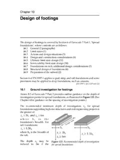
4 DENSE SPT = 10 - 30 MAINLY END -BEARING (D=Anticipated depth of bearing)PARTLY FRICTION + PARTLY END BEARINGMAINLY FRICTIONLIMESTON FORMATIONM. STIFF SPT = 4 - 15V. STIFF SPT = 15 - 32 HARD SPT > 32 DENSE / VERY DENSE SANDSOFT SPT < 4 WEATHERED ROCK / SOFT ROCKNOISE + VIBRATION; COUNTER MEASURES REQUIREDBELOW PILE CAPROCK (RQD > 70%)DENSE SPT = 30 - 50 COHESIVE SOILCOHESIVELESS SOILSOIL WITH SOME BOULDERS / COBBLES (S=SIZE)ABOVE PILE CAPDESIGN CONSIDERATIONSTYPE OF PILELEGEND :8x?INDICATES THAT THE PILE TYPE IS SUITABLEINDICATES THAT THE PILE TYPE IS NOT SUITABLEINDICATES THAT THE USE OF PILE TYPE IS DOUBTFUL OR NOT COST EFFECTIVE UNLESS ADDITIONAL MEASURES TAKENFIG 2 : PILE SELECTION CHARTSite Visit and SI PlanningSite VisitSite VisitThings To Look For ..zAccessibility & Constraints of Site zAdjacent Structures/Slopes, Rivers, Boulders, etczAdjacent Activities (eg excavation)zConfirm Topography & Site ConditionszAny Other Observations that may affect DESIGN and CONSTRUCTION of FoundationSubsurface Investigation (SI) Subsurface Investigation (SI) PlanningPlanningzProvide Sufficient Boreholes to get Subsoil ProfilezCollect Rock Samples for Strength Tests (eg UCT)zIn-Situ Tests to get consistency of ground (eg SPT)zClassification Tests to Determine Soil Type ProfilezSoil Strength Tests (eg CIU)zChemical Tests (eg Chlorine, Sulphate, etc)Typical CrossTypical Cross--Section at Hill Site Section at Hill Site Ground LevelBedrock LevelVery Hard Material LevelHard Material LevelGroundwater LevelEXISTING GROUND LEVELW ater TableC 2, 2 Clayey LayerC 3 , 3C 1 , 1 BHBHBHP erched WTSeepageCROSS SECTIONP lacing Boreholes in Limestone AreaszStage 1.
5 Preliminary Carry out geophysical survey (for large areas)zStage 2: Detailed - Boreholes at Critical Areas Interpreted from Stage 1zStage 3: During CONSTRUCTION - Rock Probing at Selected Columns to supplement Stage 2 Pile DesignPILE DESIGNPILE DESIGNA llowable Pile Capacity is the minimum of :1) Allowable Structural Capacity2) Allowable Geotechnical Capacitya. Negative Skin Frictionb. Settlement ControlPILE DESIGNPILE DESIGNS tructural consideration Not overstressed during handling, installation & in service for pile body, pile head, joint & shoe. Dimension & alignment tolerances (common defects?) Compute the allowable load in soft soil (<10kPa) over hard stratum (buckling load) Durability assessmentPile Capacity DESIGN Pile Capacity DESIGN Structural CapacityStructural CapacityzConcrete PilezSteel PilezPrestressed Concrete PileQQallall = x = x ffcucu x Ax AccQQallall = x = x ffyy x Ax AssQQallall = (= (ffcucu PrestressPrestress after loss) x Aafter loss) x AccQall = Allowable pile capacityfcu = characteristic strength of concretefs = yield strength of steelAc = cross sectional area of concreteAs = cross sectional area of steelSPT Blow Count per 300mm PenetrationCollection of SI DataCollection of SI DataPile Capacity DESIGN Pile Capacity DESIGN Geotechnical CapacityGeotechnical Capacity40005010015020025030035026242220 1816141210864201210864200501001502002503 00350400 Depth (m)Upper BoundLower BoundDesign Line (Moderately Conservative)
6 Depth Vs SPT-N Blow Count05010015020025030035040026242220181 6141210864201210864200501001502002503003 5040005010015020025030035040026242220181 6141210864201210864200501001502002503003 50400 Upper BoundLower BoundDesign LineUpper BoundLower BoundDesign LineDepth (m)Depth Vs SPT-N Blow CountSPT Blow Count per 300mm PenetrationDepth (m)Depth Vs SPT-N Blow CountSPT Blow Count per 300mm PenetrationCollection of SI DataCollection of SI DataPile Capacity DESIGN Pile Capacity DESIGN Geotechnical CapacityGeotechnical CapacityModerately Conservative Moderately Conservative DESIGN ParametersDesign ParameterszEurocode 7 definition: Characteristic value of a geotechnical parameter shall be selected as a cautious estimate of the value affecting the occurrence of the limit state In other words, moderately conservativeModerately Conservative Moderately Conservative DESIGN ParametersDesign ParameterszIf at least 10 test results are available: A value of below the mean of the test results provides a useful indication of the characteristic value1.
7 Contribution to Discussion Session , XIV ICSMFE, Hamburg, Balkema, Schneider H R (1997) Definition and determination of characteristic soil properties. Discussion to ISSMFE Conference, Extracted from Prof. Brian Simpson s Course Note (2-day Course on Eurocode 7 Geotechnical DESIGN to EC7, 13-14 November 2007, PJ, Malaysia).Extracted from Prof. Brian Simpson s Course Note (2-day Course on Eurocode 7 Geotechnical DESIGN to EC7, 13-14 November 2007, PJ, Malaysia). Piles installed in a group may fail:Piles installed in a group may fail: Individually As a blockPile Capacity DESIGN Pile Capacity DESIGN Geotechnical CapacityGeotechnical Capacity Piles fail individually When installed at large spacingPile Capacity DESIGN Pile Capacity DESIGN Geotechnical CapacityGeotechnical Capacity Piles fail as a block When installed at close spacingPile Capacity DESIGN Pile Capacity DESIGN Geotechnical CapacityGeotechnical CapacityPile Capacity DESIGN Pile Capacity DESIGN Single Pile CapacitySingle Pile CapacityPile Capacity DesignPile Capacity DESIGN Factor of Safety (FOS)Factor of Safety (FOS)Factor of Safety (FOS) is required forzNaturalvariations in soil strength & variations in soil strength & compressibilitycompressibilityPile Capacity DesignPile Capacity DESIGN Factor of Safety (FOS)Factor of Safety (FOS)Factor of Safety is (FOS)
8 Required forzzDifferent degree of Different degree of mobilisationmobilisationfor shaft for shaft & for tip& for tipLoadSettlement 5mmqsmobqbmobLoadSettlement 5mmqsmobqbmobPile Capacity DESIGN Pile Capacity DESIGN Factor of Safety (FOS)Factor of Safety (FOS)PartialPartial factors of safety for shaft & base factors of safety for shaft & base capacities respectivelycapacities respectivelyzzFor shaft, use (typical)For shaft, use (typical)zzFor base, use (typical)For base, use (typical)zz Qsu + =Pile Capacity DesignPile Capacity DESIGN Factor of Safety (FOS)Factor of Safety (FOS)GlobalGlobal factor of safety for total ultimate factor of safety for total ultimate capacitycapacityzzUse (typical)Use (typical)zz Qsu + =Pile Capacity DESIGN Pile Capacity DESIGN Factor of Safety (FOS)Factor of Safety (FOS)zzCalculate using Calculate using BOTHBOTH approaches approaches (Partial & Global)(Partial & Global)zzChoose the Choose the lower lower of the of the QQallallvaluesvaluesQQuu = Q= Qss + + QQbbOverburden Soil LayerQs = skin friction Qb = end bearingQu = ultimate bearing capacity Pile Capacity DESIGN Pile Capacity DESIGN Single Pile CapacitySingle Pile CapacityQu =.
9 Sus .As + sub .Nc .AbQsuQbuQu = Ultimate bearing capacity of the pile a = adhesion factor (see next slide)sus = average undrained shear strength for shaftAs = surface area of shaft sub = undrained shear strength at pile baseNc = bearing capacity factor (taken as ) Ab = cross sectional area of pile basePile Capacity DESIGN Pile Capacity DESIGN Single Pile Capacity : In Cohesive SoilSingle Pile Capacity : In Cohesive SoilPile Capacity DesignPile Capacity DESIGN Single Pile Capacity:Single Pile Capacity: In Cohesive SoilIn Cohesive SoilAdhesion factor (Adhesion factor ( ) ) Shear strength (SShear strength (Suu ) ) (McClelland, 1974)(McClelland, 1974)Adhesion FactorSu (kN/m2) /SuPreferred DESIGN LineMeyerhofFukuokaSPT Nfsu = (kPa)su = ( + )*50 (kPa) fsu = .su (kPa) Between SPT N and Correlation Between SPT N and ff susufsu vs SPT N010203040506070809010011005101520253035 4045 SPT Nfsu (kPa)MeyerhofFukuokaPile Capacity DesignPile Capacity DESIGN Single Pile Capacity:Single Pile Capacity: In Cohesive SoilIn Cohesive SoilzValues of undrained shear strength, sucan be obtained from the following:9 Unconfined compressive test 9 Field vane shear test 9 Deduce based on Fukuoka s Plot (minimum su)Deduce from SPT-N values based on MeyerhofPile Capacity DesignPile Capacity DESIGN Single Pile Capacity:Single Pile Capacity: In Cohesive SoilIn Cohesive SoilNOTE: Use only direct field data for shaft friction prediction instead of MeyerhofModified Meyerhof (1976):Ult.
10 Shaft friction = Qsu (kPa)Ult. Toe capacity = Qbu 250N (kPa)or 9 su (kPa)(Beware of base cleaning for bored piles ignore base capacity if doubtful)Pile Capacity DesignPile Capacity DESIGN Single Pile Capacity:Single Pile Capacity: In Cohesive SoilIn Cohesive SoilModified Meyerhof (1976):Modified Meyerhof (1976):zzUltUlt. Shaft Friction = . Shaft Friction = QQsusu ( (kPakPa))zzUltUlt. Toe Capacity= . Toe Capacity= QQbubu 250N 250N 400N 400N ((kPakPa))Pile Capacity DesignPile Capacity DESIGN Single Pile Capacity:Single Pile Capacity: In In CohesionlessCohesionless SoilSoil0200400600201612840 Depth (m)0100200300400500 Load (kN)201612840 Pile Capacity DesignPile Capacity DESIGN QsuQbu Qsu + Qbu0200400600201612840 Depth (m)0100200300400500 Load (kN)2016128400200400600201612840 Depth (m)0100200300400500 Load (kN)2016128400200400600201612840 Depth (m)0100200300400500 Load (kN)201612840 Qsu + (m)0100200300400500 Load (kN)201612840 Qsu + Method (SPTempirical Method (SPT--N)N)Shaft : Shaft : ffsusu = = KKsusu SPTSPT--NNTip Tip : : ffbubu = = KKbubu SPTSPT--NNFrom Malaysian experience:From Malaysian experience:KKsusu = = to 60 (depending on workmanship)= to 60 (depending on workmanship)Pile Capacity DesignPile Capacity DESIGN Single Pile Capacity:Single Pile Capacity.