Transcription of Pipe Design for Small Rural Systems - …
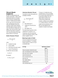
1 pipe Design for Small Rural Systems Conversion psiPN8800kPa 6psiPN 0 000kPa 45psiPN 250kPa 8 psiPN 6 600kPa232psiPN202000kPa290psiPN252500kPa 363psiSystem DesignPipe system Design requires careful thought and a thorough understanding of the requirements and operating many Rural areas advice can be sought from professional designers or the relevant State Department of Primary Industries which provides a Design survey at minimal or no cost. PPI recommends that for large or complex Systems that their advice is guide will be of benefit for Small Systems or for giving an understanding as to what is involved for larger Systems .
2 Under no circumstances can PPI be held responsible for the system Design derived from this guide or from advice give by PPI ConsiderationsThe basis of system Design is to ensure the most cost effective solution that meets all the performance in all good designs, the solution can only be as good as the information available. So often it is the first step, the information gathering step, that is rushed or not given enough emphasis. It is not accurate enough to assume that "the land is flat" or that "about 000 gallons per hour will be enough".
3 These assumptions may lead to a system failure or a reduction in the system choice or pipe diameter and pressure rating (PN) is determined by assessing the following factors; The flow or output required. The system pressure (constant or peak). The elevation changes along the pipe line. system allowance to enable pipes to stay full or drain. The friction losses caused by the pipes. Ground conditions: rocky, sandy etc. Temperatures involved for OutputWater supply to stock feed troughs is usually at very low pressures, but the flow must be calculated to match the drinking requirements of the irrigation generally requires high pressures and the total flow rate needs to be matched to the total capacity of the the output is determined the pipe sizes can be diameter pipes carry more water and higher pressures move water more quickly.
4 Remember that flow is proportional to area not the pipe diameter increases the cross sectional area by a factor or four. Significant increases in flow can be achieved by increasing one pipe PressurePressure is simply the force applied by the fluid across a certain acting on a drum full of water will push the water out if a hole is drilled in the are a mechanical means of applying force (pressure) to a pipe is manufactured in various pressure ratings to withstand different system pressures.
5 pipe with a high pressure rating has thicker walls and is therefore more expensive. Once the pressure is known the correct pressure rating of pipe can be selected to minimise the pressure can be controlled by the selection of the appropriately sized pump when pumping from a dam or " pipe carries four times as much water as 1" pipePressure ConversionmultiplyMPa 000 kPaBar 00 kPaMetre Head 0 kPapsi kPa divide Pressure Conversion Chart2" 1" 1300 661 4172 ElevationThe relative elevation of the pipe line from the source must be known so that pressure variations and
6 Vacuum air relief valves can be allowed pressure in the total pipe line must be considered before selecting the class of pipe . The pressure will vary along the length of pipe if it is at different pipe may 'suck flat' if a vacuum is present in the system . A vacuum is caused when water is allowed to flow down a pipe when the highest point is blocked To understand the forces involved it is often useful to think of the suction or force that is created when you place your hand over the drain when emptying a bath.
7 The force is quite strong yet the drop in distance is very most common occurrence of a vacuum in Rural Systems is on pipe lines running downhill from a storage tank or valve at the uphill tank is turned off but the water remaining in the pipe is still being acted upon by gravity and is trying to flow out of the pipe . Since neither air nor water can enter at the top, a vacuum is created and the pipe is 'sucked flat'.This is simply rectified by either placing an air relief valve immediately after the valve or using a valve at the output end.
8 Please refer to the diagram above. Another occurrence of vacuum in Rural pipe lines is where the pipe line crosses over undulating crest of each hill accumulates air that has been dissolved in the water and after a period of time becomes a trap. An air relief valve should be placed at the top of every change in undulation. Generally speaking, either allow the pipes to drain or keep them in the pipe system causes the pipe to "suck flat"Stage 1 Valve turned offStage 3 pipe "sucks" flatStage 2 Water continues to flowThe addition of an air relief valve allows air to enter the system and the pipe remains 1 Valve turned offStage 4 pipe remains roundStage 2 Water continues to flowStage 3 Air enters via relief valveFriction LossFrictional forces act between the water and the pipe the frictional force or losses are not taken into
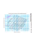
9 Account it is possible to have a system where the total frictional forces along the length of the pipe are greater than the force or pressure at the source. In this case the water would be restricted from flowing to the end of the friction loss is calculated using either the metric or imperial pipe friction these charts the friction loss is expressed in "head loss metres of water per thousand metres of pipe ".Always remember that the friction loss calculated by using the chart must be scaled to the length of the system (ie if a loss of 20m was calculated on the chart this would equate to a loss of 40m over a pipe 2km long or 0m over a pipe long).
10 The sample calculations included will show how the charts are to avoid "sucked" flat pipe the most common pipe system 1300 661 41735km (5000m)ss5000gals/dayNew Dam50mARV = Air Relief ValveGV = Gate ValveGVARVTop LevelA Small dam is being added to a paddock to supplement the drinking water form some stock. A polyethylene pipe line is to be used to transfer water from the main storage dam to the new dam. The new dam is 50m below the storage dam and they are 5km apart. The stock require 5000 gallons each day.