Transcription of PLAXIS
1 PLAXISCONNECT Edition 2D - Tutorial manual - Dry excavation using a tie back wall [ADV]Last Updated: March 16, 2021 1 Dry excavation using a tie back wall [ADV]This example involves the dry construction of an excavation. The excavation is supported by concrete diaphragmwalls. The walls are tied back by prestressed ground 2D allows for detailed modelling of this type of problem. It is demonstrated in this example how groundanchors are modelled and how prestressing is applied to the anchors. Moreover, the dry excavation involves agroundwater flow calculation to generate the new water pressure distribution. This aspect of the analysis isexplained in Modelling ground anchors. Generating pore pressures with a groundwater flow calculation. Displaying the contact stresses and resulting forces in the model.
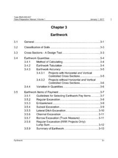
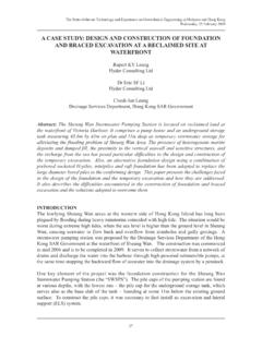
2 Scaling the displayed excavation is 20 m wide and 10 m deep. 16 m long concrete diaphragm walls of m thickness are used toretain the surrounding soil. Two rows of ground anchors are used at each wall to support the walls. The anchorshave a total length of m and an inclination of (2:3). On the left side of the excavation a surface load of10 kN/m2 is taken into relevant part of the soil consists of three distinct layers. From the ground surface to a depth of 23 m there isa fill of relatively loose fine sandy soil. Underneath the fill, down to a minimum depth of 15 m, there is a more orless homogeneous layer consisting of dense well-graded sand. This layer is particular suitable for the installationof the ground anchors. The underlying layer consists of loam and lies to a large depth.
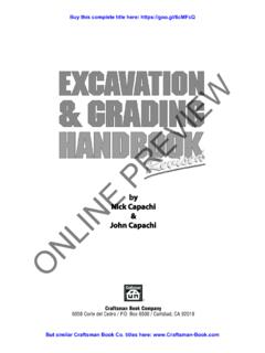
3 15 m of this layer isconsidered in the m20 m2 m10kN/m2 Final excavation levelGround anchor3 m4 m3 m5 mLoamSandSiltFigure 1: Excavation supported by tie back wallsPLAXIS2 PLAXIS 2D - Tutorial manual - Dry excavation using atie back wall [ADV]Create new the Input program and select Start a new project from the Quick start dialog the Project tabsheet of the Project properties window, enter an appropriate the Model tabsheet keep the default options for Model (Plane strain), and Elements (15-Node). the model Contour to xmin = 0 m, xmax = 100 m, ymin = 0 m, ymax = 30 the default values for units and the constants and press OK to close the Project properties the soil stratigraphyTo define the soil the Create borehole button and create a borehole at x = Modify soil layers window pops three soil layers to the borehole.
4 Locate the ground level at y = 30 m by assigning 30 to the Top level ofthe uppermost layer. The bottom levels of the layers are located at 27, 15 and 0 m, the Head to 23 layer stratigraphy looks like this:Figure 2: The Modify soil layers windowDry excavation using a tie back wall [ADV]Create new projectPLAXIS3 PLAXIS 2D - Tutorial manual - Dry excavation using atie back wall [ADV]Create and assign material data setsThree data sets need to be created. The materials have the following properties:Table 1: Soil and interface propertiesParameterNameSiltSandLoamUnitG eneralMaterial modelModelHardeningsoilHardeningsoilHard eningsoil-Type of material behaviourTypeDrainedDrainedDrained-Soil unit weight above phreatic level unsat161717kN/m3 Soil unit weight below phreatic level sat202019kN/m3 ParametersSecant stiffness in standard drainedtriaxial testE50ref20 10330 10312 103kN/m2 Tangent stiffness for primaryoedometer loadingEoedref20 10330 1038 103kN/m2 Unloading / reloading stiffnessEurref60 10390 10336 103kN/m2 Power for stress-level dependency (constant)
5 Cref'105kN/m2 Friction angle '303429 Dilatancy angle 040 Poisson's ratio ur' for normal set-USDAUSDAUSDA-Model-VanGenuchtenVanGe nuchtenVanGenuchten-Soil type-SiltSandLoam-Dry excavation using a tie back wall [ADV]Create and assign material data setsPLAXIS4 PLAXIS 2D - Tutorial manual - Dry excavation using atie back wall [ADV]ParameterNameSiltSandLoamUnit< 2 m - 50 m - parameters - Use defaults-From datasetFrom datasetFrom dataset-Permeability in horizontal in vertical strength-ManualManualRigid-Strength reduction gap closure-YesyesyesInitialK0 determination-AutomaticAutomaticAutomati c-Over-consolidation pressurePOP0025 three data sets for soil and interfaces with the parameters given in Table 14 (on page 4). the material data sets to the corresponding soil layers (Figure 64 (on page 3)).
6 Define the structural elementsThe creation of diaphragm walls, excavation levels, ground anchor and surface load is described the Structures tab to proceed with the input of structural elements in the Structures define the diaphragm wall and interfaces:A diaphragm wall with the following material properties has to be defined:Dry excavation using a tie back wall [ADV]Define the structural elementsPLAXIS5 PLAXIS 2D - Tutorial manual - Dry excavation using atie back wall [ADV]Table 2: Material properties of the diaphragm wall (plate)ParameterNameValueUnitMaterial type-Elastic-Isotropic-Yes-Axial stiffnessEA112 10 6kN/mBending stiffnessEI120 10 3kNm2/mEquivalent 's ratio the Structures mode, model the diaphragm walls as plates passing through (40 30) - (40 14) and (60 30) -(60 14).
7 The plates in the the Selection explorer click on view will change displaying a drop-down menu and a plus button next to it:Figure 3: Material assignment in the Selection the Add button .A new empty material set is created for the material data set for the diaphragm walls according to the properties are listed in Table 15 (onpage 6). The concrete has a Young's modulus of 35 GN/m2 and the wall is m positive and negative interfaces to the geometry lines created to represent the diaphragm define the excavation levels:The soil is excavated in three stages. The first excavation layer corresponds to the bottom of the silt layer and itis automatically created. To define the remaining excavation the second excavation phase by drawing a line through (40 23) and (60 23). the third excavation phase by drawing a line through (40 20) and (60 20).
8 Dry excavation using a tie back wall [ADV]Define the structural elementsPLAXIS6 PLAXIS 2D - Tutorial manual - Dry excavation using atie back wall [ADV]Defining the ground anchorA ground anchor can be modelled by a combination of a node-to-node anchor and an embedded beam. Theembedded pile simulates the grouted part of the anchor whereas the node-to-node anchor simulates the freelength. In reality there is a complex three-dimensional state of stress around the grout body which cannot besimulated in a 2D coordinates and material properties of the anchor and grout body are listed in the tables 3: Node to node anchor coordinatesAnchor locationNameFirst pointSecond pointTopLeft(40 27)(31 21)Right(60 27)(69 21)BottomLeft(40 23)(31 17)Right(60 23)(69 17)Table 4: Properties of the anchor rod (node-to-node anchor)ParameterNameValueUnitMaterial type-Elastic-Axial stiffnessEA500 10 3kNOut-of-plane 5: Grout coordinatesAnchor locationNameFirst pointSecond pointTopLeft(31 21)(28 19)Right(69 21)(72 19)BottomLeft(31 17)(28 15)Right(69 17)(72 15)Table 6.
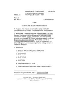
9 Properties of the grout body (embedded beam rows)ParameterNameValueUnitMaterial type-Elastic-Dry excavation using a tie back wall [ADV]Define the structural elementsPLAXIS7 PLAXIS 2D - Tutorial manual - Dry excavation using atie back wall [ADV] 106kN/m2 Unit weight 0kN/m3 Beam type-Predefined-Predefined beam type-Massive circular Skin resistanceDistributionLinear-Tskin, end, max400kN/mTskin, end, max400kN/mLateral resistanceLateral resistanceUnlimited-Base resistanceFmax0kNInterface stiffness factorDefault the node-to-node anchors according to Table 16 (on page 7). an Anchor material data set according to the parameters specified in Table 17 (on page 7). the anchors in the drawing area. Assign the material data set by selecting the correspondingoption in the Material drop-down menu in the Selection the grout body using the Embedded beam row button according to Table 18 (on page 7).
10 The Grout material data set according to the parameters specified in Table 19 (on page 7) and assign itto the grout the Behaviour of the embedded beam rows to Grout bodyFigure 4: Embedded beam rows in the Selection explorerThe connection with the anchor will be automatically (keep <Ctrl> pressed while selecting) the top node-to-node anchors and embedded and select the Group option in the context the Model explorer expand the Groups that a group is created composed of the elements of the top ground excavation using a tie back wall [ADV]Define the structural elementsPLAXIS8 PLAXIS 2D - Tutorial manual - Dry excavation using atie back wall [ADV] on Group_1 in the Model explorer and type a new name ( GroundAnchor_Top). the same steps to create a group and to rename the bottom ground the precise stress state and interaction with the soil cannot be modelled with this 2D model, it ispossible in this way to estimate the stress distribution, the deformations and the stability of the structure on aglobal level, assuming that the grout body does not slip relative to the soil.