Transcription of PLL Performance, Simulation, and Design
1 PLL Performance, Simulation, and Design1/RCrystalReferenceK 1/NVoltage ControlledOscillator( VCO )OutputFrequency( Fout )Charge Pump/Phase-FrequencyDetector ( PFD )LoopFilterFrequencyDividersLow PassFilterZ(s)ByDean BanerjeeCopyright 1998 National SemiconductorPLL Performance, Simulation, and Design Copyright 1998 National Semiconductor2 PLL Performance, Simulation, and Design Copyright 1998 National Semiconductor3 Table of ContentsPart s All of this PLL stuff? Charge Pump PLL with a Passive Filter 7 Part IIPLL PerformancePhase Noise Sources in a PLL System 11 Discusses the causes of phase noise and how to roughly predict RMS Phase Error and it s Calculation 19 Discusses the meaning, calculation, and significance of RMS phase Spurs and their Causes 24 Addresses the causes of reference spurs and what can be done about Spurs and their Causes 34 Addresses different types of spurs, their causes.
2 And their Response of PLL Frequency Synthesizers 42 Addresses in depth lock time issues and derives all relevant of the Phase/Frequency Detector for the Armchair 57 PhilosopherDiscusses the how s and why s of the operation of the III PLL DesignMethods for Passive Loop Filter Equations for PLL Design 65 Gives Design equations that do not use any approximations exceptfor the continuous time approximation. Uses numerical Loop Filters for Optimal Attenuation 74 Discusses how to choose the value of ATTEN in an optimal Fourth Order Filter Design 79 Discusses the theory and Design adding additional filtering for reference Performance, Simulation, and Design Copyright 1998 National Semiconductor4 More Information on Passive Loop Filter Effect of Various Filter Parameters on Reference Spurs for a 86 Second Order FilterActive Filters for high voltage Tuning for a Simple Method for high voltage Tuners 89 Discusses how to add an op amp for an active filter using the Do of a Loop Filter using the r and p pins 90 Discusses using these pins with an op amp to Design an active filter13 Designing an Active filter with the Do pin and Op Amp 96 Discusses using an op amp with components in the feedback Design for a high voltage Tuner 100 Discusses a Design using transistors to increase the tuning voltage to the VCOPart IV Supplemental Detect Circuit Construction and Analysis 109 Discusses how to build a more sensitive lock detect circuit and how it PLL
3 Design and Performance Issues 114N value determination, peaking and phase margin, impedance matching,sensitivity, concluding 117 Lists various PLL terms and symbols used in this book with their Diagrams 121 PLL Performance, Simulation, and Design Copyright 1998 National This Book is Intended ForThis book assumes experience working with passive loop filters. The basic designequations for the passive loop filter is in National Semiconductor s Application Note AN-1001 An Analysis and Performance Evaluation of a Passive Filter Design Technique for ChargePump Phased Locked Loops . Many of the basic concepts and Design equations are given in thisapplication note. This is available on the web at It is also true thatsome of these papers are very specific to National Semiconductor s PLLs. However, most of theconcepts apply to all PLLs. As the author of this book, I endorse National Semiconductor PLLsfor reasons including their high quality, extensive portfolio, and excellent phase noiseperformanceHow this Book Came to BeI first became familiar with PLLs when I started working for National Semiconductor asa wireless applications support person.
4 When dealing with customer support, I have noticed thatmany questions are asked over and over. Instead of creating the same response over and over, itmade more sense to create a document, worksheet, or program to address the question in greaterdetail and just re-send the file. These files have evolved into a massive collection of papers,programs, excel worksheets, and mathcad programs. This is a collection of papers that havebeen used to explain many of the things that were observed in practice that were previously Value of a Rigorous Mathematical ApproachMany of these questions can be answered with a greater understanding of the problemand the mathematics involved. By approaching problems in a rigorous mathematical way onegains a greater level of understanding, a greater level of satisfaction, and the ability to apply theconcepts learned to other problems.
5 An excellent online mathematical reference is Eric sTreasure trove of mathematics at: ~eww6n/ of the formulas that I have seen used before contain many approximations and arehard to find a justification of how they were derived. Also, many of these formulas are fromtextbooks that are out of date and make assumptions not true of the PLL system today. Fromthese, rules of thumb are born that work only under certain conditions. All of these papers havesome sort of computer simulation tool associated with them. I have also compared a lot of thesesimulated results against real book is a collection of my learnings on PLLs. There are other people who I haveworked with in National Semiconductor who have aided in my understanding of PLLs and alsoin the editing of this would like to thank Ian Thompson for the insights that he has provided, particularly inthe area of phase noise and the noise characteristics of the phase-frequency detector.
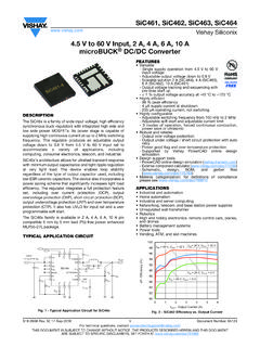
6 I wouldlend special thanks Bill Burdette for all the editing, commenting, and RF insights that he hasprovided that has made this book possible. I would also like to thank Bill Keese for his insights,particularly in AN-1001, which serve as a basis for a lot of these documents. I would also like tothank Yuko Kanagy for her helpful Performance, Simulation, and Design Copyright 1998 National s All of this PLL Stuff?Figure 1 The Basic PLLB asic PLL OperationThe PLL ( Phased Locked Loop ) starts with a stable crystal reference frequency. Thisfrequency is divided by R to a lower frequency, which is called the comparison frequency. Thisis one of the inputs to the phase detector. The phase-frequency detector outputs a current whichhas an average DC value that is proportional to the phase error between the comparisonfrequency, and the output frequency after it is divided by the N one takes this average DC current value and multiplies it by the impedance of the loopfilter, then the input voltage to the VCO ( voltage Controlled Oscillator ) can be found.
7 Notethat the loop filter is a low pass filter, often implemented with discrete components. This loopfilter is application specific, and much of this book is devoted to the loop filter. This tuningvoltage adjusts the output phase of the VCO, such that when divided by N, is equal to the phaseof the comparison frequency. Since phase is the integral of frequency, this implies that thefrequencies will also be matched, and the output frequency will be given by:OutputFrequencyNRXTAL== (1)This applies only when the PLL is in the locked state, and does not apply during the timewhen the PLL is adjusting to the locked state. For a given application, R is typically fixed, andthe N value can easily be that the PLL technically refers to the entire system shown in figure 1, however,sometimes the PLL is meant to refer to the entire system except for the crystal and VCO.
8 This isbecause these components are difficult to integrate on a PLL synthesizer 1/NVCOFoutCharge Pump/Phase-FrequencyDetector ( PFD )Loop FilterPLL Performance, Simulation, and Design Copyright 1998 National Charge Pump PLL with a Passive Loop FilterWhy this Book Focuses on Charge Pump PLLsThis book focuses all of it s effort s on charge pump PLLs. The reason for doing so is that theseare the vast majority of the PLLs in the market today, and that is what I have experience indealing with. The charge pump PLL offers many advantages over the classical voltage phasedetector PLL including an infinite pull in range and zero steady state phase error. There is also aconsiderable amount of literature that discusses in great detail features that are specific only tothe voltage phase detector. This allows more time to discuss other features of the PLL, withoutgetting caught up in the details of the phase detector.
9 The charge pump PLL also allows one touse a passive filter and still have many of the benefits of using the active filter with the voltagephase detector. I have always recommended passive filters because they are lower cost and haveno added noise. The exception to this case is when the VCO tuning voltage needs to be higherthan the PLL can supply in this case, an active filter is Classical voltage Phase DetectorIn the past, active filters have been emphasized for several reasons that are explained indepth in Floyd Gardner s classical book Phaselock Techniques. Many of these concepts stillapply to the charge pump PLL, while many others, such as the steady state phase error do XOR gate and the mixer are both discussed as practical ways to implement a phase Gardner s book, the following classical active loop filter topology is 1 Classical Active Loop Filter Topology for a voltage Phase DetectorThe Modern Phase Frequency Detector with Charge Pump and it s AdvantagesThe phase frequency detector with charge pump combination offers several advantagesover the voltage charge pump and has all but replaced it.
10 The phase-frequency detector andcharge pump are usually integrated on the PLL chip. using this approach completely bypassesissues of steady state phase error and hold in range. The PLL with this combination can becompared to it s predecessor as is done in figure 2. Note that the circuit shown below with thebox drawn around it integrates the functionality of the OP AMP. Note it is necessary to dividethe phase detector voltage gain by R1 in order convert the voltage gain to a current VCOPLL Performance, Simulation, and Design Copyright 1998 National Semiconductor8 Figure 2 Passive Loop Filter with Charge PumpThe capacitor C1 is added, because it reduces the spur levels significantly. Also, thecomponents R3 and C3 can optionally be added in order to further the reference spur level. Notethat this passive filter has the OP AMP functionality included.